Home » How to 4 Wire LS Wiring Harness Conversion: Full Guide
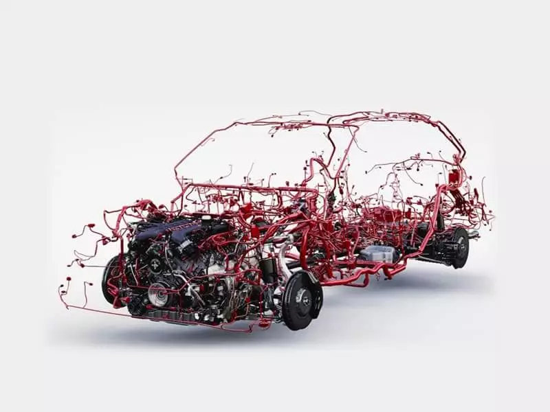
A 4-wire conversion involves streamlining a GM LS engine—which originally relied on a complex OEM wiring harness—so that it can operate in the target vehicle using only four core wires. It sounds simple, but when you actually get to work, every step—from power distribution and ECM power supply to ground loops and signal interfaces—is fraught with details that can easily lead to pitfalls.
This guide will walk you through the entire process of modifying the fourth-generation LS wiring harness in detail. From deciding whether to modify the stock wiring harness or use a custom harness, to identifying key circuits, rerouting wires, integrating the ECU and fuel system, addressing calibration and anti-theft requirements, and testing the wiring harness before the first start-up.
What Does This LS Wiring Conversion Query Mean?
“4-wire” likely does not refer to a wiring harness with only four wires, but rather to the wiring harness conversion scheme for the fourth-generation LS engine.
If you interpret it as “streamlining the LS engine wiring harness down to four wires,” you’re off track from the very beginning.
The correct approach is to confirm which generation the engine actually is, what type of crankshaft position trigger system it uses, and which ECM/PCM is employed. Only by cross-referencing these three factors can you determine whether the existing wiring harness is suitable for conversion.
Tip: Do not rely solely on the engine name or model year to make a determination, as there are early Gen IV engines that use the 24x crankshaft trigger system; not all Gen IV engines are simply equivalent to 58x engines.
Interpreting “4 wire” as a Gen 4 LS harness conversion
If your goal is a Gen 4 LS wiring harness conversion, you’ll need to reorganize the engine wiring harness from the original or donor vehicle so that it can independently handle engine control and the necessary vehicle interfaces in another vehicle.
When transplanting an engine, you must distinguish between the wires essential for engine operation and those specific to the original donor vehicle, and then reorganize these connections according to the new vehicle platform—rather than simply cutting a large number of wires.
Tip: When you see a product labeled “4-wire LS swap,” we recommend that you first confirm exactly what that means. It may describe a simplified wiring method for a specific connector, or it may simply be a typo where “Gen 4” was written as “4-wire.”
How Gen III 24x and Gen IV 58x systems differ
| Check Point | Gen III | Gen IV | Practical Tip |
|---|---|---|---|
| Crank Reluctor | Often 24x | Often 58x | Always check the actual reluctor. Generation alone is not enough. |
| Crank Sensor | 24x matched sensor | 58x matched sensor | Sensor, reluctor, and ECM must work as one system. |
| Cam Signal | Common 1x | Common 4x | Check the crank + cam combination, not just the crank signal. |
| ECM / PCM | P01 / P59 | E38 / E67 and others | Identify the controller before touching the harness pinout. |
| Throttle | Application-dependent | DBW is common | Match the throttle body, pedal, and ECM. |
| CAN / Modules | Vehicle-dependent | CAN is more common | If you need gauges or transmission communication, check CAN early. |
| VVT / AFM | Engine-dependent | Common on some engines | Do not assume all LS engines have the same control circuits. |
| Harness Match | 24x + matching PCM | 58x + matching ECM | Verify ECM, sensors, reluctor, and pinout together. |
| My Rule of Thumb | Do not choose a harness by “Gen III” or “Gen IV” alone. | Start with the engine, reluctor, ECM, sensors, and pinout. Then decide what can be changed. | |
Tip: The term “Common” in the table is used only to help you quickly establish a decision-making logic; it does not represent an absolute correspondence. Do not treat “Gen III = 24x, Gen IV = 58x” as the sole basis for purchasing wiring harnesses.
Should You Rework the Factory Harness or Buy a Standalone Harness?
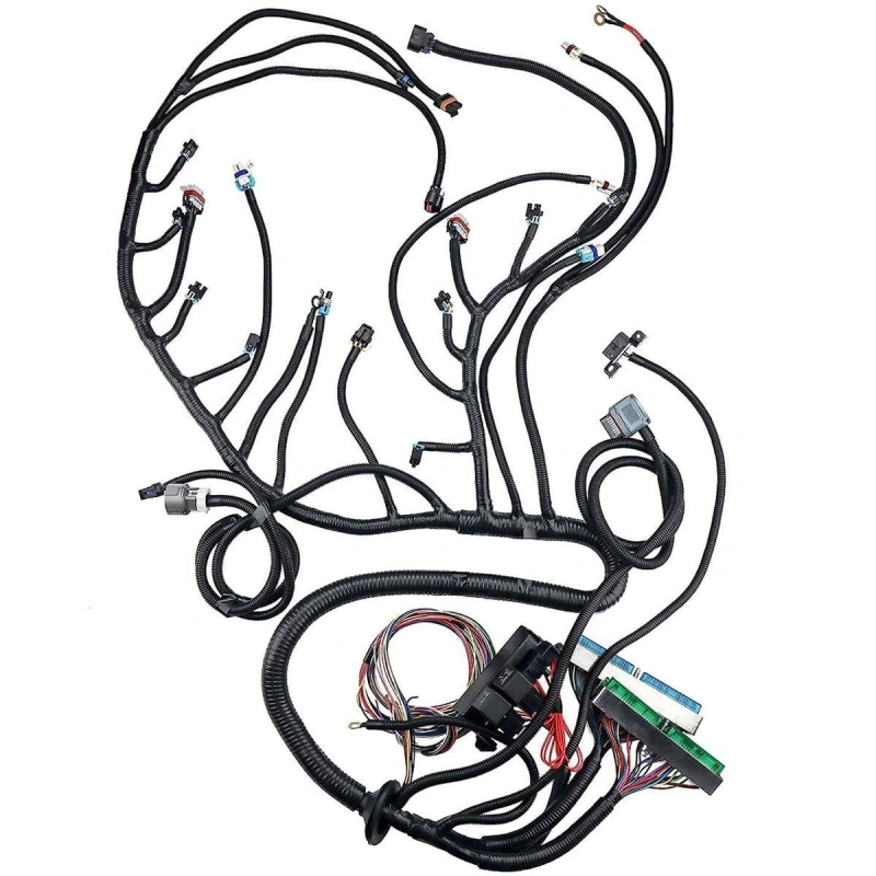
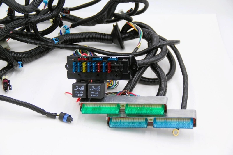
There are two possible approaches to an LS engine swap: retaining the original wiring harness and modifying it, or purchasing a standalone harness designed specifically for your engine and transmission configuration.
The deciding factors are whether your engine, ECM/PCM, transmission, vehicle features, emissions requirements, budget, timeline, and your own ability to handle electrical issues are all compatible.
Compare cost, time, documentation, emissions features, serviceability, and risk
| Decision Factor | Modify Factory Harness | Standalone Harness |
|---|---|---|
| Initial Cost | Usually lower if you already have a complete donor harness. | Usually requires an additional purchase. |
| Upfront Time | More time for tracing, removing, and reorganizing circuits. | Usually faster, but vehicle-side wiring is still required. |
| Skill Required | Higher. You need to understand the factory wiring and pinout. | Lower, but compatibility still needs to be checked. |
| Documentation | Factory wiring diagrams and pinouts are essential. | Follow the harness manufacturer's wiring and installation guide. |
| Factory Features | Easier to retain original functions and connectors. | Usually focused on the engine and transmission. |
| Emissions | Easier to retain related factory circuits. | Confirm the required emissions-related connections are supported. |
| Serviceability | Depends heavily on the quality of your rewiring work. | Usually easier to label, trace, and service. |
| Layout | Can be bulky until unnecessary branches are removed. | Usually cleaner and better suited to swaps. |
| Customization | High. You can tailor the harness to the vehicle. | Depends on the supplier's customization options. |
| Main Risk | Wrong wire removal, splicing, crimping, or grounding. | Wrong specification or assuming it is completely plug-and-play. |
| Best For | A complete donor harness and someone willing to trace the circuits. | Reducing rewiring work and getting the swap running sooner. |
| Practical Tip | Keep the factory harness if you understand its pinout and want to retain more functions. | Choose standalone when simplicity and a clean layout matter more than retaining every factory circuit. |
When professional harness conversion is the better decision
If your wiring harness configuration is complex, or if you cannot accurately determine the connections between the engine, reluctor, ECM/PCM, throttle body, accelerator pedal, and transmission, a professional wiring harness modification may be more appropriate.
What Must You Identify Before Modifying the Harness?
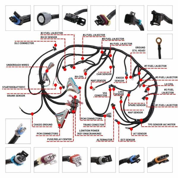
Before you begin cutting wires, disconnecting terminals, or rerouting LS wiring harnesses, create a complete system configuration list. Electrical configurations may vary significantly depending on the model year, engine type, ECM, throttle body, transmission, and donor vehicle.
Engine, reluctor pattern, ECU, throttle, transmission, pedal, and donor year
Step 1: Identify the specific engine model and its origin.
Record the engine family, displacement, engine number/code, original vehicle model, and approximate year. This is because sensor locations, throttle body types, cam signals, crankshaft reluctors, VVT, and AFM/DOD configurations may vary.
Step 2: Confirm the reluctor pattern.
The reluctor is a position-encoding toothed disc on the crankshaft; the crankshaft position sensor reads it to inform the ECM of the engine’s current RPM and crankshaft position. Common LS systems include two crankshaft signal configurations: 24x and 58x, and the ECM must be able to recognize the corresponding signal.
Tip: Do not equate engine generations directly with reluctor types. It is best to cross-check this information against the crankshaft sensor, engine configuration, and ECM model.
Step 3: Verify the ECU/ECM/PCM.
These terms all refer to the engine control computer, though GM has used different names across various eras and systems. You need to record the specific model, part number, and original vehicle application of the controller, rather than simply writing “LS ECU.” For example, GM’s documentation explicitly matches specific LS1 ECUs with specific engines and wiring harnesses, indicating that the ECM and harness are not interchangeable, generic components.
Step 4: Verify the throttle body and accelerator pedal.
If your LS uses DBW (Drive-by-Wire), the accelerator pedal does not directly control the throttle via a mechanical cable; instead, a pedal sensor provides input to the ECM, which then controls the throttle actuator. The throttle body, accelerator pedal, ECM, and corresponding wiring harness must be verified as a single system.
Step 5: Verify the transmission.
Do not wait until after you have modified the engine wiring harness to decide which transmission to use. GM’s performance documentation lists the control schemes required for electronically controlled automatic transmissions such as the 4L60-E, 4L65-E, 4L80-E, and 4L85-E; therefore, the transmission model will directly affect your wiring harness and control system configuration.
Step 6: Record the donor year.
The year helps you locate the correct wiring diagram, ECM, sensors, connectors, and vehicle communication configuration. It helps narrow down the options, but you’ll still need to verify them using the actual part numbers and pinouts.
Connector labels, pinouts, diagrams, fuse blocks, and missing components
| Inspection Item | What to Confirm | Why It Matters | Common Mistake |
|---|---|---|---|
| Connector Labels | Connector labels and their corresponding components. | Prevents similar connectors from being confused. | Identifying connectors only by shape or color. |
| Pinouts | Pin number, wire function, and destination. | Provides the basis for correct rewiring. | Wiring by color or using another LS pinout. |
| Wiring Diagrams | Engine control, power, grounds, fuses, and relays. | Shows which circuits to keep, remove, or reroute. | Using a diagram for the wrong vehicle or ECM. |
| Fuse Blocks | Fuses, relays, protection circuits, and loads. | Ensures critical circuits have proper power and protection. | Removing unfamiliar fuses or relays. |
| Missing Components | ECM/PCM, throttle body, pedal, sensors, and transmission controller. | Missing components can affect system compatibility. | Replacing a missing component with a few wires. |
Which Circuits Must a Gen 4 LS Swap Keep?
A standalone harness is not just a few wires left over “to start the engine.” The engine control system still requires a complete set of circuits, including a stable power supply, ground connection, sensors, fuel injectors, ignition coils, electronic throttle, and diagnostic communication.
You’ll need to verify which wires to keep on a case-by-case basis, depending on your ECM/PCM, engine configuration, and transmission.
ECU power, ignition power, grounds, injectors, coils, sensors, and OBD-II
ECU power and ignition power are fundamental control circuits.
The ECU/ECM is the core of the entire engine electronic control system and requires a stable constant power supply from the battery as well as a power input controlled by the ignition switch. GM’s control system installation documentation explicitly lists battery power and ignition switch input as connections required for normal engine operation.
Grounds should not be treated as ordinary return paths.
If you are rebuilding the wiring harness, you should restore the engine ground and control module ground in accordance with the original factory circuit design for the specific engine and ECM; do not arbitrarily combine or relocate them.
How to determine this: First, locate the wiring diagram corresponding to your ECM, engine, and wiring harness version, then verify the source, destination, and purpose of each ground connection.
Injectors and ignition coils are part of the core actuator circuits for engine operation.
The ECM relies on inputs such as crankshaft, camshaft, and load to control fuel injection and ignition; therefore, fuel injectors and ignition coils should not be treated as accessories that “can be connected later.” GM’s Gen IV engine control system documentation explicitly lists the connection requirements for fuel injectors, ignition coils, and position sensors such as crankshaft and camshaft sensors.
Sensors must be verified based on the actual engine and ECM configuration.
Common examples include CKP, CMP, MAP, MAF, ECT, as well as signals related to the throttle body and accelerator pedal. Oxygen sensors and knock sensors may also be part of the ECM’s control and diagnostic system.
The OBD-II port must be retained.
It serves as a critical interface for diagnosing the ECM, reading trouble codes, and monitoring real-time data. For vehicles undergoing their first LS swap or requiring future repairs, retaining the diagnostic port will significantly simplify troubleshooting.
Starter, fuel pump, cooling fans, throttle pedal, tachometer, and speed signals
Distinguish between the starter circuit and the ECM control circuit.
The starter is responsible for bringing the engine up to a speed at which combustion can occur, while the ECM is responsible for controlling fuel injection and ignition based on signals such as CKP and CMP once the engine is running.
Retain the fuel pump control.
The ECM can control the fuel pump via a fuel pump relay or other control methods to ensure the engine receives the proper fuel supply under normal operating conditions.
Please note: The ECM typically outputs control signals or a designed pump control circuit; you should not directly connect a high-current fuel pump to any ECM pin.
Reserve the cooling fan circuit.
The ECM controls the fan relay based on coolant temperature and specific calibration settings. Some Gen IV systems offer single-stage or two-stage fan control; you must first confirm the ECM’s output configuration before deciding whether the vehicle will use one or two fan control circuits. Do not directly connect a high-power fan motor to the ECM’s low-current control output.
The throttle pedal is a component in Gen IV LS modifications that is particularly prone to errors.
DBW throttle. The Gen IV LS may no longer use the separate TAC module found in the Gen III DBW system; instead, the throttle pedal connects directly to the ECM. Therefore, you cannot simply mix and match throttle pedals from different model years or with different ECMs.
The tachometer and speed signal are part of the vehicle’s interface circuitry.
While they may not be core actuators essential for the engine’s basic combustion process, they are crucial for the vehicle’s normal operation. The RPM signal can be fed to the stock or aftermarket tachometer, while the speed signal may be used by the instrument cluster, ECM, or electronic transmission for functions such as speed display and shift control.
Automatic-transmission and standalone-controller requirements
| Circuit | Keep? | Main Function | How to Check |
|---|---|---|---|
| ECM Power | Required | Provides ECM power and ignition logic. | Check the ECM wiring and fuse/relay diagrams. |
| Engine / ECM Grounds | Required | Provides a stable electrical return path. | Follow the original grounding layout. |
| Injectors / Ignition Coils | Required | Controls fuel injection and ignition. | Match the engine, ECM, injectors, and harness. |
| CKP / CMP Sensors | Required | Provides engine position and speed data. | Match the actual engine and ECM setup. |
| Electronic Throttle / Pedal | Required for DBW | Controls the electronic throttle. | Confirm ECM, throttle, and pedal compatibility. |
| OBD-II | Recommended | Supports diagnostics and live data. | Confirm ECM-to-DLC communication. |
| Fuel Pump | Required | Supplies fuel to the engine. | Check ECM control, relay, and fuse setup. |
| Cooling Fans | Keep | Helps maintain engine temperature. | Check ECM fan outputs and cooling system. |
| Starter | Required | Cranks the engine for starting. | Follow the vehicle's starter circuit. |
| Tachometer | Keep | Provides engine RPM to the gauge. | Check ECM output and gauge compatibility. |
| Speed Signal | Configuration dependent | Provides vehicle speed information. | Check VSS use by the ECM, gauge, and transmission. |
| Automatic Transmission Control | Required for electronic AT | Controls shifting and transmission functions. | Match the transmission and TCM/ECM setup. |
| Emissions Circuits | Do not remove blindly | Supports emissions control and diagnostics. | Check vehicle use, regulations, and ECM calibration. |
Which Factory Circuits Can Be Removed or Repurposed?
First, you’ll need to go through the circuit diagram wire by wire to determine its function—to figure out whether a particular wire is for the engine control system or just for a specific body function in the original vehicle.
In modern GM powertrains, the ECU doesn’t operate in isolation; instead, multiple modules—including the ECM, BCM, ABS module, instrument cluster, and transmission control module—communicate with each other via the CAN bus and work in coordination.
The proper approach to standalone wiring harness modifications isn’t to focus on which wires are thick or thin, or which connectors are large or small, but rather to first understand the communication relationships between the vehicle’s various modules.
Donor-body, emissions, security, chassis, and unused accessory circuits
| Item | Problem to Solve | What to Check | Common Mistake |
|---|---|---|---|
| Fuse | Overcurrent protection | Match the fuse rating to the circuit and wire. | Replacing a blown fuse with a larger one. |
| Relay | Controls higher loads | Separate the control and load circuits. | Making the ECM carry excessive load current. |
| Splice | Electrical and mechanical connection | Check crimping, mechanical support, and sealing. | Twisting wires, taping them, and hiding them in the harness. |
| Ground | Reliable return path | Check the ground point, wire, mounting, and contact. | Using any body bolt as a common ground. |
| Heat Protection | Protects insulation from heat | Check heat-source clearance and shielding. | Routing wires against exhaust parts with only standard tape. |
| Branch Protection | Prevents abrasion and vibration damage | Secure branches and protect them from sharp edges. | Leaving wires unsupported or against sharp sheet metal. |
Legal and calibration checks before deleting emissions hardware
Emissions-related circuits cannot be treated the same way as ordinary idle circuits; streamlining the wiring harness and removing the emissions system are two entirely different matters. The emissions system includes the catalytic converter, EGR, and the entire set of calibration programs in the ECU that control fuel injection, monitor emissions, and run OBD diagnostics.
You need to clarify three things first: what the regulations in your area require, whether this car is for street use or exclusively for the track, and whether your engine configuration actually needs these functions.
How Do You Rework the Harness Step by Step?
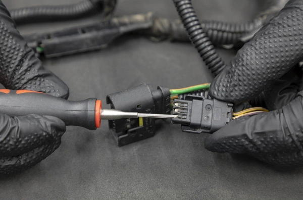
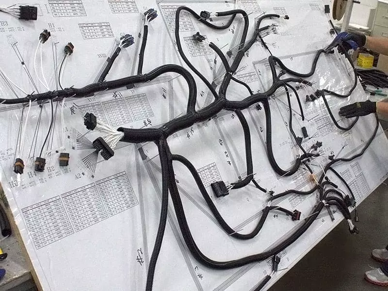
The correct approach is to treat the original wiring harness as a complete circuit map. First, verify the function of each connector, each circuit, and each power branch one by one. Once you have a clear understanding, decide which ones to remove, which ones to relocate, and which ones to rewire.
Document, label, unwrap, trace, depin, reroute, branch, protect, and terminate
Step 1: Start by taking photos to document everything.
Note the locations of connectors, the routing of the wiring harness, the lengths of the branches, and the positions of the ECM and various sensors. For wires you plan to remove, also record their connectors, pin numbers, and destinations. This isn’t redundant—it provides a traceable reference for every subsequent step. If you rely on memory to guess where wires connect after disassembly, you’re bound to run into problems sooner or later.
Step 2: Remove the corrugated tubing and tape section by section.
Expose the internal wiring harness. Don’t unwrap everything all at once; if the harness is complex, work in sections to better preserve the original branching relationships.
Step 3: Trace the wires.
Follow each wire you plan to modify to confirm where it comes from, which branching points it passes through, and where it ultimately goes.
Don’t rely solely on wire color to determine function—the same color can serve completely different purposes in different circuits. Cross-reference the ECM pin definitions, circuit diagrams, and the actual wiring harness item by item.
Step 4: Only proceed with depinning after confirming that a wire truly needs to be removed.
This is especially important for multi-pin connectors; preserve the connector and terminal structure to facilitate future restoration or reconfiguration.
Step 5: Proceed to Reroute and Branch.
Do not bundle all wires together simply for aesthetic reasons; wires in high-heat areas, high-current wires, and sensitive signal wires must be routed separately. After relocating the ECM, you must reconsider firewall openings, branch lengths, and serviceability.
Step 6: Protection and Termination
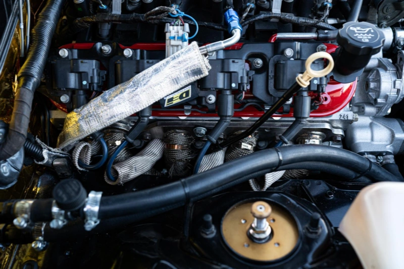
Use corrugated tubing, heat-resistant sleeving, high-temperature tape, protective sheathing, and wear-resistant perforations, as well as crimp terminals and seals. The engine compartment is exposed to high temperatures, vibration, oil, and moisture; it’s not enough to simply ensure “electrical continuity.” Long-term mechanical protection and environmental sealing are equally important.
Fuse and relay sizing, splice methods, grounding, and heat protection
| Item | Problem to Solve | Key Check | Common Mistake |
|---|---|---|---|
| Fuse | Overcurrent protection | Match the fuse to the circuit and wire. | Installing a larger fuse when it keeps blowing. |
| Relay | Controls higher loads | Separate the control circuit from the load circuit. | Making the ECM carry an unsuitable load current. |
| Splice | Electrical and mechanical connection | Check crimp quality, strain relief, and sealing. | Twisting wires and wrapping them with tape. |
| Ground | Reliable return path | Check the ground point, wire, fastening, and contact. | Using any convenient body bolt as a common ground. |
| Heat Protection | Protects wire insulation | Keep wiring away from exhaust heat and add proper shielding. | Routing wires against exhaust components with only tape. |
| Branch Protection | Prevents abrasion and vibration damage | Secure branches and protect them from sharp metal edges. | Leaving harnesses loose or touching sheet metal. |
| My Practical Rule | Protect the circuit at the fuse, control the load with the relay, secure every splice and ground, and keep the harness away from heat and sharp edges. | ||
How Are the ECU, Fuel System, Fans, and Chassis Connected?
The power supply layer, the ECU control layer, and the vehicle interface layer. The power supply layer is responsible for supplying power to the ECM, actuators, and high-current loads. The ECU control layer is responsible for controlling fuel, ignition, the throttle, fans, and other systems based on sensor inputs. The vehicle interface layer is responsible for connecting the engine system to the starter, instrument cluster, diagnostics, charging, and other vehicle body functions.
Tip: The ECM, engine, and transmission configurations used in different Gen 4 LS models are not entirely identical, so you should not directly copy the entire wiring harness from a single donor vehicle. The correct approach is to first identify the ECM model and engine configuration, then verify each power, control, and signal circuit according to the corresponding wiring diagram.
Switched power, constant power, crank request, pump relay, fan relays, and outputs
Switched power and constant power
Constant power is a continuous power supply from the battery.
Switched power is the power supplied to the ECM when the ignition key or vehicle start switch is in the appropriate position.
Since their functions differ, you cannot simply combine all ECM power wires into a single wire.
Crank Request is a signal, not a power source.
The actual high-current power supply for the starter motor is handled by the vehicle’s starting circuit and the starter relay/solenoids; it has nothing to do with the ECM.
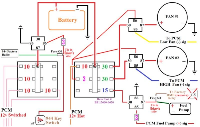
The fuel pump relay follows a very typical “control circuit + load circuit” structure.
The ECM is responsible for controlling the fuel pump relay, while the fuel pump’s high current is supplied through a fuse and the relay contacts.
The logic for the fan relay is similar.
The ECM controls the cooling fan relay based on engine temperature and specific calibration, while the high current required by the fan motor is supplied by a separate fuse and relay load circuit. You should determine this based on the actual ECM pinout and the vehicle’s cooling system, rather than assuming that all Gen 4 LS engines use the same fan wiring configuration.
Tip: It is important to note that ECU output and power output are not the same thing. A particular output pin on the ECM may simply be a control signal; it does not mean that this pin can directly supply operating current to the fuel pump or fan.
Interfaces for gauges, diagnostic port, charging, and vehicle controls
| Interface | Main Function | Key Check | Common Mistake |
|---|---|---|---|
| Gauges | Provides RPM, vehicle speed, temperature, and other information. | Confirm ECM and gauge signal compatibility. | Connecting directly without checking signal types. |
| Diagnostic Port | Reads diagnostic trouble codes and live data. | Keep the communication lines between the ECM and OBD-II port. | Removing the OBD-II port to simplify the harness. |
| Charging System | Supplies power from the alternator and charges the battery. | Confirm the alternator and voltage regulation method. | Connecting only the main power wire and ignoring control circuits. |
| A/C Request | Provides the A/C request signal to the ECM. | Confirm whether the ECM requires this signal. | Connecting only the compressor without the ECM request signal. |
| Brake / Clutch Input | Provides brake or clutch status to the ECM. | Confirm requirements based on the ECM and vehicle functions. | Assuming these signals are unrelated to engine operation. |
| Speed Signal | Provides vehicle speed information to the gauges, ECM, or transmission. | Confirm the signal source and compatibility. | Considering only the gauges and ignoring other modules. |
| MIL | Displays engine fault status. | Confirm the interface method between the ECM and gauges. | Removing the MIL to simplify the harness. |
What Calibration and Security Changes May Be Required?
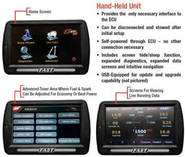
Once the LS wiring harness conversion is complete, simply connecting the wires correctly does not guarantee that the system will function properly. You also need to verify that the calibration settings in the ECM match the vehicle’s actual configuration.
VATS, transmission settings, fan control, gear ratio, tire size, and diagnostics
| Item | Main Function | When to Check | Key Check |
|---|---|---|---|
| VATS | Handles engine anti-theft verification. | When using a used OEM ECM. | Confirm the ECM matches the target vehicle's anti-theft system. |
| Transmission | Matches the transmission control logic. | When using an electronically controlled automatic transmission. | Confirm the ECM/TCM, transmission, and VSS configuration. |
| Fan Control | Controls the cooling fans. | When replacing the ECM, fans, or control method. | Confirm the ECM control signal matches the relay or controller. |
| Gear Ratio | Corrects vehicle speed and related calculations. | When the rear axle gear ratio changes. | Confirm the ECM calibration matches the actual gear ratio. |
| Tire Size | Affects vehicle speed calculation. | When installing different-size tires. | Confirm the vehicle speed calculation is correct. |
| Diagnostics | Reads diagnostic trouble codes and live data. | Recommended for all LS swaps. | Confirm the ECM, OBD-II DLC, and communication lines work properly. |
How Do You Test Before First Start?
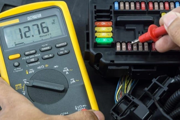
Before starting the LS engine for the first time, you should first check continuity, isolation, fuse protection, ground voltage drop, and pinout. The purpose of this is not to guarantee that the engine will start, but to rule out any wiring harness issues as much as possible before applying power.
Continuity, isolation, fuse protection, ground-drop, pinout, and reference checks
Step 1: Check Continuity.
Verify that the critical circuit is indeed continuous from the connector to the target terminal. A continuity test is suitable for checking for open circuits, but you should not rely solely on the multimeter’s beep to determine that the circuit is completely correct, as this does not prove that the circuit is connected to the correct pin.
Step 2: Perform an Isolation Check.
Focus on confirming that there are no unintended short circuits between power lines, signal lines, and ground.
Step 3: Check the fuses and relays.
Fuses are designed to protect circuits and loads, so you should verify the protection method based on the actual circuit and wiring harness design.
Step 4: Check for excessive voltage drops.
You need to focus on inspecting the main ground connections between the engine, the ECM, and the vehicle chassis, rather than simply relying on static resistance measurements to conclude that the ground connection is “fine.”
Step 5: Double-check the pinout and reference materials.
The correct sequence is: ECM model → connector → pin number → wire function → destination.
Tip: Do not rely solely on wire colors, connector shapes, or wiring diagrams for a different LS model found online, as electronic systems may vary across different engines, ECMs, and vehicle models.
First-power and no-start troubleshooting sequence
When powering on for the first time, it is recommended that you first verify that all required engine and vehicle connections have been made before connecting the battery and ignition power.
If the first start attempt fails, do not immediately disconnect the wires again. Troubleshoot in the following order: Power → Ground → Communication → Inputs → Outputs.
If the engine does not turn over at all, prioritize checking the start control, battery power, ground connection, and starter circuit. If the engine turns over but does not start, focus on the ECM power supply, crankshaft/cam signals, fuel supply, fuel injection, and ignition control.
If the engine starts but stalls immediately, further inspect the anti-theft status, sensor inputs, and ECM calibration.
Frequently Asked Questions
Q1: Can a Gen 3 harness run a Gen 4 LS engine?
It may not be directly compatible. There may be differences between Gen 3 and Gen 4 engines in terms of crankshaft/cam signals, ECM, and throttle control. You’ll need to first verify the engine, ECM, and reluctor (signal gear) configurations before determining whether compatibility can be achieved through rewiring or signal conversion.
Q2: Do all Gen 4 LS engines use the same ECU connectors?
No. The ECM/PCM and connectors used in Gen 4 LS engines vary depending on the engine, model year, and control system. For example, different systems may use different connectors and pinout configurations. Therefore, you cannot assume that ECU connectors are identical simply because they are “Gen 4”; you must verify the specific ECM pinout.
Q3: Can the factory fuse box be retained?
Yes, but it depends on the specific vehicle and wiring harness configuration. The factory fuse box can continue to provide power and protection for circuits such as the ECM, fuel pump, and fan; however, the body circuits of the donor vehicle are typically quite complex. If retaining the factory fuse box makes it difficult to clearly distinguish between engine and body circuits, a separate engine fuse/relay box may be easier to maintain.
Q4: What causes an LS swap to crank but not start?
The most common areas to check include ECM power supply or ground connection, crankshaft/camshaft signals, fuel supply, fuel injection control, the ignition system, the anti-theft system status, and ECM calibration mismatches. You can start by verifying that the ECM is receiving power properly, then use OBD-II to read trouble codes and real-time data, focusing on confirming whether the correct engine position signal is being received during startup.
Conclusion: How to 4 Wire LS Wiring Harness Conversion: Full Guide
There is no definitive answer as to whether the 4-wire conversion solution should be adopted for the Gen 4 LS harness simplification: If you are seeking a lightweight, simplified electrical architecture and the target vehicle already has a dedicated fuel pump relay and fan control solution, the 4-wire conversion is a reliable choice.
The final decision should be based on the target vehicle’s electrical architecture, usage scenarios, and diagnostic requirements.
As a professional wiring harness manufacturer and supplier, Linkwings offers a full range of solutions—from OEM-spec terminals to customized standalone harnesses—supporting both standardized and customized harness configurations for Gen 3 to Gen 4 LS platforms, helping you find the optimal harness solution for various transplant scenarios. We welcome you to contact us!

Nicole
The founder of Linkwings Electronics.
10+ Years Experience | 1000+ Global Projects Completed
Specialized in:
- Custom Wire Harness Assembly
- Automotive & Industrial Cable Harness Manufacturing
- Precision Crimping & Terminal Processing
- OEM / ODM Wire Harness Solutions
Need help with your project?
Let Linkwingselec deliver your next wire harness solution.