What Is a Wire Harness for Car Stereo? Complete Guide
Home » What Is a Wire Harness for Car Stereo? Complete Guide
If you’re replacing your car stereo or installing an aftermarket stereo, you may come across a confusing component: the car stereo wire harness.
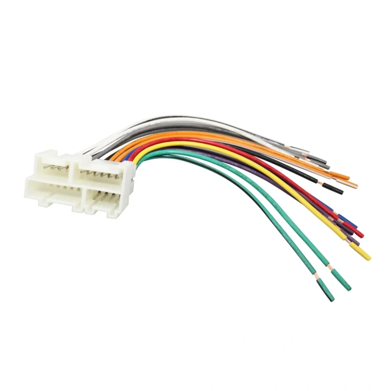
A car stereo wire harness is a set of wires organized and connected according to specific electrical functions, used to establish a reliable electrical connection between the vehicle’s original wiring and the stereo head unit.
In this guide, we’ll explain in detail what a car stereo wire harness is, what it does, how it connects to the vehicle, the different types available, and how to choose the right harness for your installation. This will help you determine more accurately what kind of wire harness you need.
What Does a Car Stereo Wire Harness Do?
It connects the power supply, ground, speakers, and some control signals, allowing the new audio system to work properly with the vehicle’s electrical system without having to cut and splice the original wiring harness.
The short answer: a removable electrical interface
A car stereo wire harness is not the stereo itself; it organizes the circuits that need to be connected—such as power, ground, and speakers—into corresponding connectors and wires, allowing an aftermarket stereo to connect to the vehicle’s original electrical system.
Tip: Don’t assume that two connectors are compatible just because they look similar. Also, don’t determine their function based solely on the color of the original vehicle’s wires. The vehicle model, year, trim level, and factory audio system can all affect the actual configuration of the wiring harness.
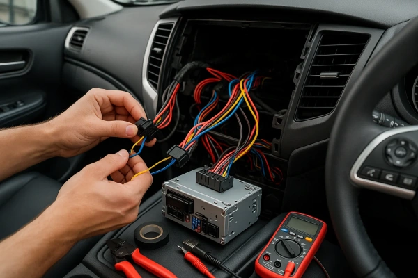
How it preserves the factory plug and simplifies installation
To install the car audio wiring harness, first connect one end of the adapter harness correctly to the wiring harness that comes with the new stereo, and then plug the other end directly into the vehicle’s original stereo connector.
This installation method offers two key advantages:
- You can connect the new audio system to the adapter harness outside the vehicle first. Once everything is organized, you can insert the entire assembly into the vehicle, providing more working space and making routing the wires much easier.
- Reversibility—if you ever want to revert to the factory audio system, simply unplug the adapter harness and plug it back into the original equipment; there’s no need to repair any cut wires.
When selecting a wiring harness, first confirm which circuits and functions need to be transmitted between the vehicle and the new audio system. Verify the vehicle’s year, make, model, specific configuration, and whether it comes with a factory-installed amplifier.
One more point deserves your special attention: a wiring harness does not automatically resolve all compatibility issues. Just because the wiring harness connector fits does not mean all functions will work properly.
Which Wires and Functions Are Typically Included?
Car audio wiring harnesses can be divided into power/control circuits and speaker circuits. When you see a wire, don’t just memorize its color—it’s more important to understand its function.
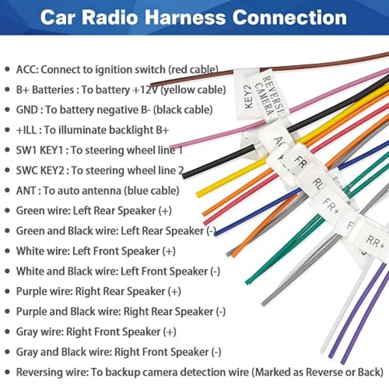
Constant power, accessory power, ground, illumination, and remote turn-on
Constant Power
This wire provides a continuous power supply to the head unit. However, its purpose is not to keep the audio system playing continuously, but to preserve your settings: the clock, preset radio stations, and equalizer preferences.
It’s important to note that “12 V” is a nominal value in automotive electrical systems; the actual measured voltage varies depending on the vehicle’s operating conditions and electrical system. Therefore, do not interpret “12 V” to mean that the voltage must always measure exactly 12.00 V.
Accessory power
This wire is controlled by the ignition switch. When you turn the key to power on the vehicle, it supplies power to the head unit and turns it on. When you turn off the ignition and power is cut, the head unit turns off as well.
Please note that modern vehicles do not necessarily use a traditional ignition switch to supply power to the ACC; some are managed through the vehicle’s electronic control module. Therefore, do not look for a red wire as you would in older vehicles.
Ground
It provides a return path for the circuit, allowing current to form a complete loop.
If the ground connection is unreliable, the head unit may fail to power on, operate erratically, or experience other electrical issues. More importantly, the negative terminal of the speakers is not the same as the vehicle’s ground.
Illumination
Used to inform the head unit that the vehicle’s lighting system is on, allowing the head unit to adjust the display brightness or enter night mode based on the vehicle’s lighting status. This wire does not need to be connected in all installations.
Remote turn-on is used to control when external devices power on. It does not supply the amplifier with its main operating current; rather, it provides a control signal to let the amplifier know, “The head unit is now on, and you can start operating.”
Speaker pairs, antenna power, reverse, and parking signals
Speaker pairs
These are another set of core wires in a car audio wiring harness. Each speaker requires a pair of wires: positive (+) and negative (−).
A common mistake here is relying on the “color-coding rule” as the determining factor. You need to match “function to function,” not “color to color.”
Antenna power
This may be related to the blue wire, but it’s important to distinguish it from the blue-and-white amplifier remote wire. The blue wire is often used to control a power antenna or certain amplified antennas, while the blue-and-white wire is typically used for amplifier turn-on.
Reverse signal
Used to signal an audio head unit that supports a backup camera or related navigation features.
Note that the reverse signal and the camera video cable are two separate things: the former tells the head unit “when to switch,” while the latter transmits the camera feed.
Parking brake signal
Found in aftermarket multimedia receivers equipped with video, navigation, or specific safety features. Its purpose is to allow the head unit to detect the parking brake status; some head units may control certain functions based on this status.
Are Car Stereo Wire Colors Universal?
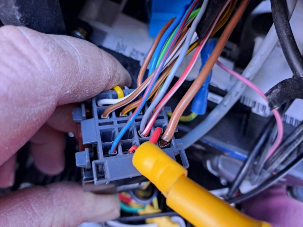
The colors of car audio wiring harnesses are not standardized worldwide.The color codes for original wiring harnesses may vary depending on the brand, model, and model year.
Common aftermarket color conventions
If this is your first time working with car audio wiring harnesses, you might wonder: “Some aftermarket head units use red, yellow, black, white, gray, green, and purple—are these colors standardized?”
The answer is: There are general conventions, but they aren’t necessarily standardized.
These colors are meant to help you identify the wiring harnesses of the aftermarket devices themselves. The safest approach is to use the colors for quick identification and the functional definitions for final confirmation.
Tip: The same color may have different additional functions depending on the product. Whether a specific device provides these wires, and whether a particular wire exists, varies based on the product design.
Why factory diagrams and pinouts still need verification
1. Schematic Diagrams and Pin Definitions
- Schematic Diagrams: Show you how the circuit is connected and what each wire does.
- Pin Definitions: Tell you the specific function of each pin on a connector.
- For vehicle-specific wiring harnesses, these two sources of information are far more reliable than “guessing functions based on wire colors.”
2. Color Codes Cannot Be Applied Across Systems
- The yellow wire on the aftermarket head unit is for constant power, but the wire responsible for constant power in the OEM connector may not be yellow at all.
- Correct Approach: Confirm which pin on the vehicle side actually provides constant power, then connect using a vehicle-specific adapter harness or verified wiring definitions—rather than simply matching “yellow to yellow.”
3. Modern vehicles are far more than just “power supply + four speakers”
- Modules such as factory-installed amplifiers, steering wheel controls, backup cameras, and CAN bus systems may all be integrated into a single connector.
- A particular pin may carry a control signal rather than a standard speaker wire; even if two connectors have the same physical shape, it does not mean their pin functions are arranged identically.
4. “Fits” ≠ “Circuit Compatibility”
- Connectors address physical connections, while pin definitions determine “what each pin is actually connected to.”
- Incorrect connections for power, ACC, ground, or speaker wires can result in the system not working at best, or blowing fuses or even damaging electrical modules at worst.
- When switching vehicle models, model years, or audio configurations, you must reconfirm the wiring definitions; you cannot simply copy the wiring from a previous vehicle.
5. Common Pitfalls with Speaker Wires
- Color combinations like white/white-black or gray/gray-black on the aftermarket end serve as good identification references, but they only apply to the aftermarket head unit side.
- The wire colors on the factory side may be completely different; do not assume that a black wire is the speaker negative terminal, and certainly do not treat all black wires as ground connections.
- The speaker negative terminal must not be connected directly to the vehicle chassis—this is explicitly emphasized by manufacturers such as Sony.
What Types of Stereo Harness Adapters Are Available?
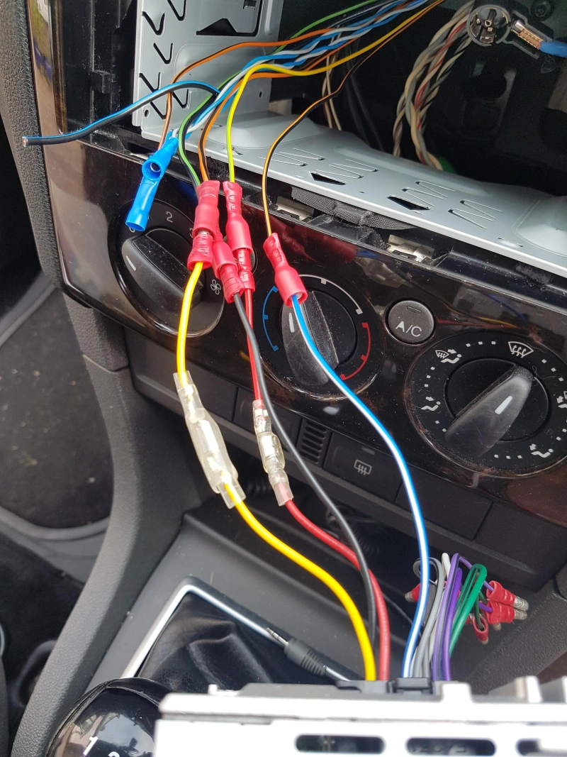
Car audio wiring harness adapters can be divided into three categories based on their functional levels:
- Basic adapters handle the connection of power, ground, and speaker wires between the head unit and the vehicle’s original wiring.
- Reverse wiring harnesses, extension harnesses, and speaker adapters are used for signal direction conversion, wire extension, or speaker channel expansion;
- Data interface adapters use protocol decoding to preserve the vehicle’s original integrated functions, such as steering wheel controls, backup camera, and alert tones.
Basic radio-to-vehicle adapters
Function of a radio-to-vehicle adapter: One end connects to an aftermarket radio, and the other end connects to the vehicle’s factory audio connector, linking the corresponding power, ground, and speaker wires on both sides.
This type of product is suitable for audio systems with relatively simple configurations.
You should note the difference between vehicle-specific and universal adapters. The connectors and wiring definitions at both ends of a vehicle-specific harness are designed for a specific vehicle model, so installation may be nearly plug-and-play. With a universal harness, you’ll need to match each functional wire to the corresponding wire on the new head unit.
Reverse harnesses, extension harnesses, and speaker adapters
| Harness Type | Main Purpose | Best Use | Selection Tips |
|---|---|---|---|
| Reverse Harness | Uses or extends the factory audio connector with minimal modification to the vehicle wiring. | When you need to connect to or convert a factory interface. | Do not confuse it with reverse signal (reverse trigger). Always check the manufacturer's definition. |
| Extension Harness | Extends the connection length of an existing harness. | When the original harness is too short due to a relocated head unit or remote module. | Check the connector, pinout, and signal type. Avoid pinching, friction, and high-temperature areas during installation. |
| Speaker Adapter | Connects factory speaker plugs to aftermarket speakers. | When the new speaker terminals do not match the factory connector. | It is mainly for connector matching. It does not handle steering wheel controls, factory amplifiers, or reverse cameras. |
| Radio Integration Interface | Handles more complex connections between the aftermarket head unit and the vehicle's electronic system. | When replacing the head unit while retaining the factory amplifier, steering wheel controls, or other vehicle functions. | Check compatibility based on the vehicle model, year, and factory configuration. |
Data interfaces for chimes, steering-wheel controls, cameras, and retained features
| Interface Type | Purpose | Use Case | Selection Tip |
|---|---|---|---|
| Data Interface | Converts vehicle signals for aftermarket radios. | Retain factory electronic functions. | Check model, year, trim, and head unit compatibility. |
| SWC Interface | Keeps steering wheel buttons working. | Retain volume, track, and phone controls. | Must match both car and radio. |
| Chime Interface | Keeps factory warning sounds. | Retain door, lights, and alert chimes. | Basic harnesses usually do not restore chimes. |
| Camera Interface | Connects the factory backup camera. | Use the original camera with a new radio. | Check video input, voltage, and reverse trigger. |
| Amplifier Interface | Retains the factory amplifier. | Vehicles with factory amp systems. | Confirm the amp type before choosing. |
| Radio Integration Interface | Combines power, amp, SWC, chime, and camera support. | Complex vehicles needing multiple factory features. | Do not judge by plug fit alone; verify required functions. |
How Do Factory-Amplified Systems Change the Harness Choice?
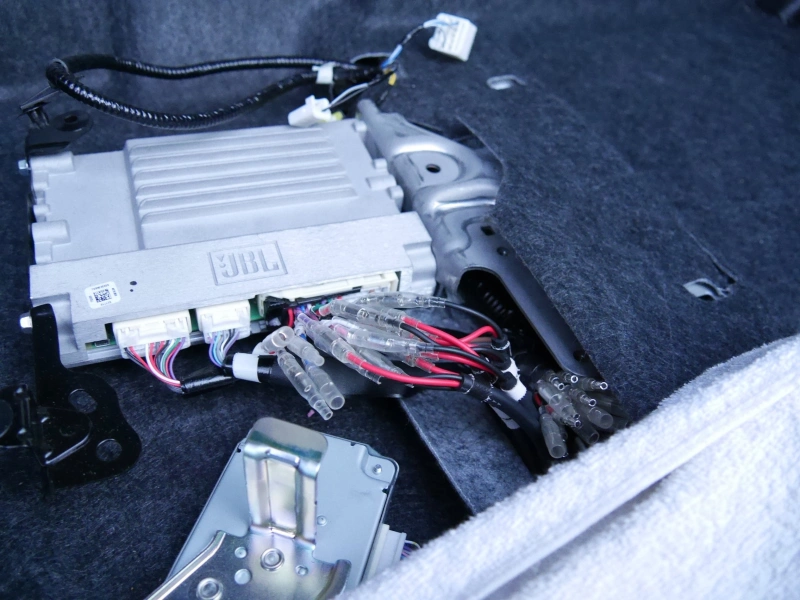
The factory amplifier is located between the head unit and the speakers; it likely amplifies the audio signal, drives the various speakers, and works in conjunction with the vehicle’s original audio system. You’ll first need to determine whether your new system will retain the factory amplifier or bypass it.
Amplifier integration versus bypass
Amplifier integration—Continue using the stock amplifier. All you need to do is ensure the new head unit outputs a signal compatible with the stock amplifier, while retaining stock features such as power-on control and steering wheel controls.
Amplifier bypass—Do not use the stock amplifier; instead, replace it with an aftermarket amplifier to drive the speakers. In this case, you’ll need a vehicle-specific bypass harness to “tap into” the speaker wiring from the factory amplifier and reconnect it to your aftermarket amplifier.
For you, the key factor is what your upgrade goals are.
- If you’re just replacing the head unit and leaving the factory audio system largely untouched → Prioritize Integration
- If you plan to install a new amplifier, replace the speakers, and add a subwoofer → We recommend Bypass
Tip: “Bypass” does not necessarily mean you can simply disconnect the factory amplifier. Other functions in some vehicles may still rely on the factory amplifier or its connections.
Line-level signals, turn-on circuits, impedance, and digital audio networks
| Key Factor | Meaning | Selection Point | Experience |
|---|---|---|---|
| Line vs. Speaker Level | Low-power signal vs. amplified output. | Identify the factory signal type first. | Do not choose LOC only because there is a factory amp. |
| Turn-on Circuit | Turns aftermarket amps on/off. | Check amp turn-on output and current. | Use a relay if multiple amps exceed remote output capacity. |
| Impedance | Speaker electrical load. | Match amp, speaker, and device ratings. | Plug fit does not mean load match. |
| Digital Audio Network | A2B or similar digital audio/control system. | Confirm whether the car uses digital audio. | Use the right DSP, interface, or T-harness. |
How Do You Choose the Correct Harness?
The key to selecting the right wiring harness lies in accurately matching the vehicle information (model year, trim level, audio package) with the aftermarket head unit model, and then checking the compatibility database to confirm that the connectors, pin assignments, and the plan for retaining the vehicle’s original functions are fully compatible.
Vehicle year, trim, audio package, factory options, and radio model
The first step in selecting a wiring harness isn’t to look at what the connectors look like, but to confirm the vehicle’s complete specifications. You need to verify the model year, make, model, trim level, and factory audio system configuration.
1. Trim Level Determines the Audio Architecture
The trim level may directly determine whether the vehicle is equipped with a factory amplifier, steering wheel controls, a factory backup camera, or a premium audio system.
Professional compatibility databases include information such as trim level, factory audio system, and navigation configuration in their matching criteria.
2. Factory Options Must Not Be Overlooked
Two vehicles of the same model year and model may differ significantly in their required interface solutions—one might lack a factory amplifier system, while the other might include one.
For certain vehicles, you must also consider the retention of factory cameras, USB ports, accessory power (RAP), audio alerts, or steering wheel controls. Different products offer varying solutions for preserving these features.
3. Radio Model Must Be Confirmed by Both Parties
When using an integration solution that involves a data interface, DSP, or a specific brand of head unit, it is not enough to simply confirm that “the vehicle-side interface can be plugged in”; you must also verify that the aftermarket head unit supports the input, output, and control functions required by that interface.
Fitment database, connector, pinout, and feature-retention checks
After confirming the vehicle configuration, the second step is to use a reliable compatibility database to find the corresponding wiring harness.
1. Compatibility Database: The First Step Toward an Accurate Match
After entering the model year, make, and model, you’ll need to further filter by trim level and factory audio system to pinpoint the correct wiring harness model.
For some models, you can use RPO codes to narrow down the options even further and avoid selecting the wrong part.
2. Connectors and Pin Definitions: Physical Connection ≠ Functional Compatibility
Connectors address whether “the plugs can physically connect,” while pin definitions address “what function each pin actually performs.”
Just because the plug shapes are the same or the plugs fit together does not mean that every pin serves the same function.
You must verify the correspondences for power, ground, speakers, amplifier controls, and other signals item by item based on the product installation instructions, the vehicle wiring diagram, or the pin definition table provided by the manufacturer.
3. Retaining Factory Features: Verify as Needed
If the goal is simply to have the aftermarket head unit play audio, the basic wiring harness may be sufficient.
If you need to retain features such as steering wheel controls, RAP, factory cameras, alert tones, or balance/attenuation controls, you must verify that the selected interface explicitly supports them.
4. Selection Decision Process
Confirm Year/Make/Model → Confirm Trim Level and factory audio configuration → Confirm Factory Options → Confirm head unit model → Search the compatibility database → Verify connectors and pin definitions → Finally, check which factory features need to be retained.
If any of these steps cannot be confirmed, it is not recommended to determine compatibility based solely on photos of connectors or product titles.
Crimping, Soldering, or Plug-and-Play: Which Is Best?
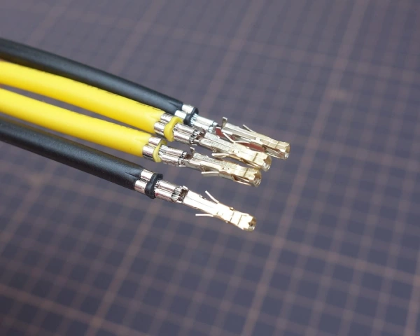
Crimping, soldering, or plug-and-play? It comes down to your personal preference: Plug-and-play sacrifices flexibility in exchange for faster installation and zero risk; crimping strikes the best balance between reliability and maintainability; soldering offers the best electrical performance but has a high learning curve and is difficult to repair.
Compare reliability, serviceability, tools, speed, and installation risk
| Factor | Plug-and-Play | Crimping | Soldering |
|---|---|---|---|
| Reliability | Stable if harness quality and pinout match. | Best for vibration when done correctly. | Good conductivity, but solder joints can crack under vibration. |
| Serviceability | Best. Easy to remove and restore to factory. | Good. Can be cut and redone. | Lowest. Harder to repair in tight spaces. |
| Tools | No special tools needed. | Requires matching terminals, wire size, and crimp tool. | Requires soldering tools and careful insulation. |
| Speed | Fastest. | Fast. | Slowest. |
| Risk | Lowest, but plug fit does not mean function match. | Medium. Poor tools or terminals cause loose connections. | Higher. Rigid joints and weak strain relief can fail over time. |
How Is a Stereo Harness Installed and Tested?
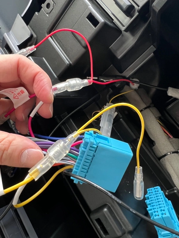
Installation Procedure: Disconnect the negative terminal of the battery → Remove the original head unit and trim panel → Align the vehicle-side end of the wiring harness with the connector and insert it → Connect the head unit end according to color or pin definitions → Ensure proper insulation and strain relief → Organize the wiring, but do not secure the head unit yet.
Testing Procedure: Reconnect the battery negative terminal → Turn on the ignition → Verify the following functions one by one: head unit power on/off, sound output from each channel, steering wheel controls, backup camera, and RAP → If any abnormalities occur, immediately turn off the power and troubleshoot → Once everything is confirmed to be working properly, slide the head unit into place and secure it.
Disconnect, map, join, insulate, secure, reconnect, and function-test
Step 1: Disconnect the Power
Turn off the vehicle and disconnect the negative terminal of the battery to prevent short circuits during installation. If the vehicle or repair manual specifies any special requirements after disconnecting the power, follow the manufacturer’s instructions first.
Step 2: Identify the Wires
Refer to the wiring harness diagram, pin definitions, or vehicle wiring diagram to identify the function of each wire individually; do not rely solely on color. Pay special attention to verifying the constant power supply, accessory power supply, ground wire, speaker output, and any control signals that need to be retained. For models equipped with factory-installed amplifiers, steering wheel controls, or other interface modules, also verify whether the corresponding interfaces already handle these functions.
Step 3: Connection
Plug-and-play harnesses: Verify that the connectors, pin assignments, and functions match between the vehicle end and the aftermarket head unit.
Custom connections: Ensure that the terminals, wire gauge, and crimping tools are compatible; the quality of the crimping directly affects long-term reliability.
Step 4: Insulation and Protection
Every connection point must be properly insulated to prevent pulling, bending, or friction. Areas potentially exposed to moisture or salt spray require sealed protection; unsealed connection points are prone to corrosion in humid environments. Additionally, provide mechanical protection and stress relief; do not subject connection points to continuous tension.
Step 5: Secure the Wiring Harness
Do not allow the wiring harness to hang loosely, and do not place it against sharp metal edges, moving parts, or high-temperature areas. Allow for reasonable movement when securing the harness, but ensure that connectors or wiring points do not bear continuous tension.
Step 6: Restore Power and Test
Reconnect the negative battery terminal and verify each function individually; do not limit testing to simply checking “whether the system turns on”:
- Head unit power supply and memory functions
- Sound output from left/right and front/rear channels
- Volume and mute controls
- Lighting controls
- Steering wheel controls
- Rearview camera
- Other factory features that need to be retained
Troubleshoot no power, no sound, noise, memory loss, and missing controls
| Issue | Check First | Practical Tip |
|---|---|---|
| No Power | Constant power, ACC, ground, fuse, connector. | Use a multimeter before blaming the head unit. |
| No Sound | Speaker wiring, factory amp, audio interface. | Check the audio signal path and factory amp setup first. |
| Noise | Ground, signal wiring, joints, cable routing. | Fix ground and signal issues before replacing the harness. |
| Memory Loss | Constant power. | Confirm constant power stays connected as required. |
| Missing Controls | SWC interface, data interface, vehicle config. | Check interface compatibility before rewiring speakers. |
What Should OEM and Installer Buyers Evaluate?
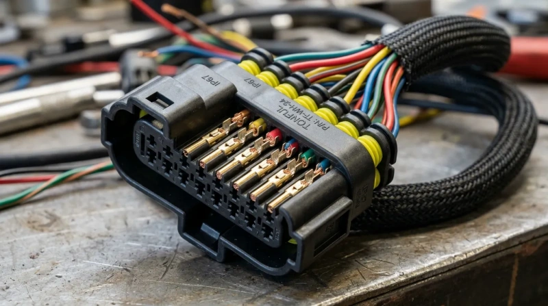
The key to evaluating the quality of a wiring harness lies in six dimensions: terminal quality, wire gauge specifications, stress relief, traceability, installation instructions, and technical support.
Terminal quality, wire gauge, strain relief, traceability, instructions, and support
If you are an OEM procurement professional or an installer responsible for the actual installation, when evaluating a wire harness, you should assess whether the terminals, wires, mechanical protection, production traceability, installation instructions, and supplier support are complete. You should also consider whether the connections will remain stable under vibration, temperature fluctuations, moisture, and long-term mechanical stress.
| Item | Check | Practical Tip |
|---|---|---|
| Terminal Quality | Terminal type, wire size, insulation, and crimp method. | Do not judge by looks. Verify specs and crimp fit. |
| Wire Gauge | Current, length, voltage drop, and terminal rating. | Thicker is not always better. Match the actual load. |
| Strain Relief | Connector lock, joint support, and harness routing. | Avoid long-term pulling, bending, or rubbing. |
| Traceability | Part number, version, batch, and product changes. | For OEM orders, choose suppliers with clear batch tracking. |
| Instructions | Fitment, connectors, pinout, steps, and function notes. | Clear pinout and install guides reduce risk. |
| Support | Fitment, pinout, troubleshooting, and technical help. | Confirm support before dealing with amps, SWC, or cameras. |
| Overall | Compatibility, electrical specs, reliability, and support. | Connect correctly, work reliably, and remain traceable. |
Frequently Asked Questions
Q1: Can you install a car stereo without a wiring harness?
Technically, yes—you can cut the wires and splice them directly to get sound. However, this is strongly discouraged. Cutting the wires compromises the integrity of the vehicle’s original wiring, making troubleshooting extremely difficult if problems arise, and may also void the warranty. The core value of a wiring harness is that it’s reversible—simply unplugging it restores the vehicle to its factory condition.
Q2: Why does an aftermarket radio need a data interface?
In many vehicle models, the head unit doesn’t simply receive analog audio signals; instead, it’s connected to digital audio buses such as the CAN bus or A2B. Functions like steering wheel controls, power-on signals, vehicle settings menus, and backup camera displays all rely on data communication. Without a data interface, these functions will all fail.
Q3: What is the blue wire on a stereo harness?
The standard definition is the amplifier remote control wire. When the head unit powers on, it outputs 12V to trigger the aftermarket amplifier to power on and off in sync. Important note: On some vehicle models, the blue or blue-and-white wire may be an antenna control wire or a lighting wire; always refer to the pin definitions rather than relying solely on color.
Q4: Can the factory amplifier be retained?
Yes, but a corresponding interface solution is required. Common approaches include using a high-to-low level converter to extract signals from the factory amplifier’s output, or using a dedicated interface with protocol decoding to preserve the factory amplifier’s complete signal chain.
Conclusion: What Is a Wire Harness for Car Stereo? Complete Guide
By now, you should have a clear understanding of the role that wiring harnesses play in car audio systems. A high-quality wiring harness is the result of precise alignment between connectors, pin assignments, vehicle configurations, and intended functionality. From searching the compatibility database to item-by-item verification of connectors and pins, and down to every detail regarding insulation, waterproofing, and stress relief—each step determines the final installation quality and long-term user experience.
Linkwings is committed to providing customers with stable, traceable, and customizable car audio wiring harness solutions. Whether you need plug-and-play, vehicle-specific harnesses or complex interface solutions requiring custom development, we offer professional-grade engineering support. Contact us today to customize your car audio wiring harness products.

Nicole
The founder of Linkwings Electronics.
10+ Years Experience | 1000+ Global Projects Completed
Specialized in:
- Custom Wire Harness Assembly
- Automotive & Industrial Cable Harness Manufacturing
- Precision Crimping & Terminal Processing
- OEM / ODM Wire Harness Solutions
Need help with your project?
Let Linkwingselec deliver your next wire harness solution.