LVDS Cable Problems: Causes, Solutions and Best Practices
Home » LVDS Cable Problems: Causes, Solutions and Best Practices
In modern electronic devices, LVDS cables are widely used in laptops, automotive display systems, industrial control equipment, and medical imaging devices. They handle high-speed, low-power data transmission tasks, and any malfunction directly impacts display quality and system stability.
Common LVDS cable issues include screen flickering, signal interference, poor contact, limited resolution, and poor environmental adaptability. These problems not only degrade product experience but may also increase maintenance costs or even pose safety risks. Understanding the common issues with LVDS cables and their root causes is a critical aspect that engineers and procurement personnel must not overlook during project design and supply chain management.
What is an LVDS Cable?
LVDS, short for Low Voltage Differential Signaling, is a technology that transmits high-speed data using low-voltage differential signaling. Unlike traditional single-ended signals, LVDS employs two conductors to carry opposite voltage signals, with the receiver detecting only the voltage difference between them. This differential transmission method significantly enhances interference resistance while enabling high-speed data transfer at hundreds of Mbps to Gbps levels with reduced power consumption.
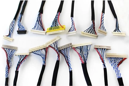
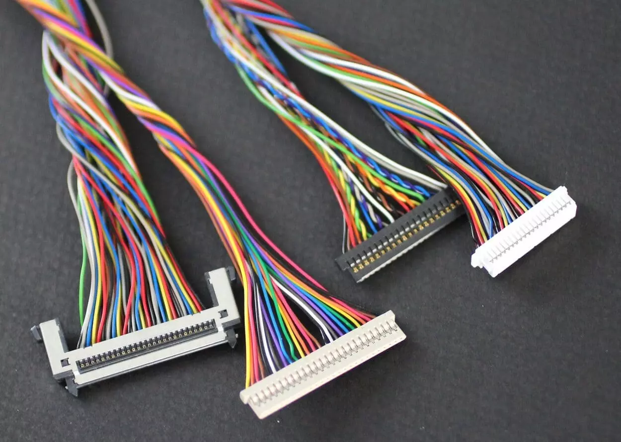
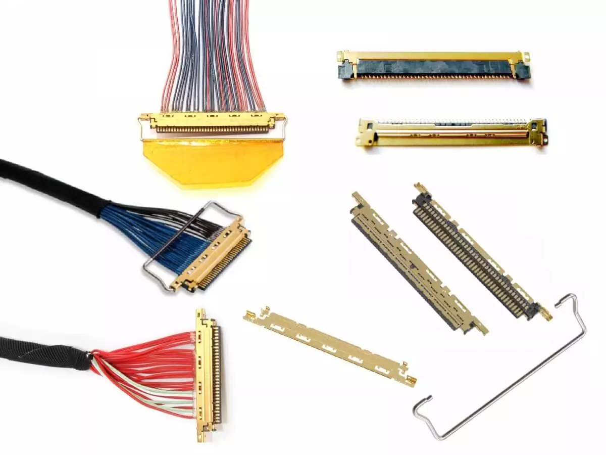
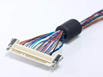
An LVDS cable is the specialized wiring designed to carry this signal. Its structure typically consists of high-purity copper conductors, twisted differential pairs, insulation layers, and shielding layers, paired with high-density connectors such as I-PEX, Hirose, or JST. Key design considerations include impedance control (typically 100Ω), shielding to suppress electromagnetic interference (EMI), and ensuring signal integrity.
Precisely because of LVDS Cable’s specialized structure and design requirements, any issues with the cable’s materials, construction, or manufacturing processes can readily cause common failures such as signal interference, image distortion, or reduced lifespan. Therefore, understanding the working principles and structural characteristics of LVDS Cable is essential for correctly identifying and resolving LVDS cable problems.
6 Common LVDS Cable Problems
In complex electronic systems, LVDC cable issues are often caused by design flaws, manufacturing deviations, or mismatched application environments. These problems not only compromise image display quality but can also lead to system failures.
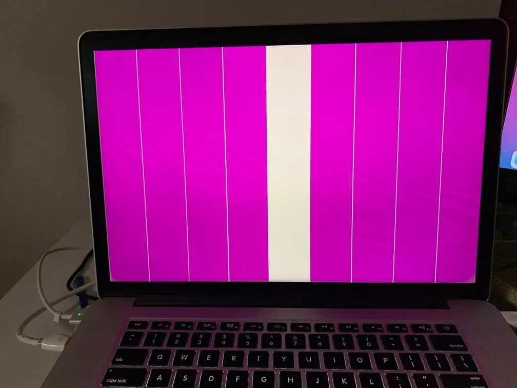
Problem 1. Signal Interference and Image Distortion
Typical Symptoms: Screen flickering, snowflake-like dots, color shift, periodic horizontal stripes, and complete blackout in severe cases.
Root Causes:
- Impedance Mismatch: LVDS differential signals require strict 100Ω impedance control. Inconsistencies in wire gauge, insulation thickness, or geometric arrangement cause signal reflection and eye diagram collapse.
- Poor Twist Quality: Inconsistent twist pitch in differential pairs creates electrical imbalance, weakening interference immunity.
- Insufficient Shielding or Grounding Errors: Inadequate shield coverage or incorrect grounding methods (e.g., floating shields or conflicting ground connections) trigger EMI issues.
Potential Risks: Impacts user experience in consumer electronics and may pose safety hazards in automotive and medical applications—e.g., distorted vehicle displays or misinterpreted medical imaging.
Problem 2. Insufficient Resolution or Bandwidth
Typical Symptoms: Screen stuttering, frame drops, blurred sections, or display failures at high resolutions or refresh rates.
Root Causes:
- Insufficient Channel Count: Single-channel LVDS cables cannot meet high-definition display bandwidth requirements.
- Inappropriate cable parameters: Conductor gauge is too thin, resulting in insufficient electrical performance and excessive high-frequency signal attenuation.
- Insufficient design margin: When cable speed approaches its upper limit, any manufacturing variation can cause transmission failure.
Potential risks: The system cannot support design specifications, requiring development rework or alternative solutions, leading to project delays and increased costs.
Problem 3. Plugging/Unplugging and Connection Issues
Typical Symptoms: Intermittent screen blackouts or flickering, loose connectors, temporary recovery after unplugging but unstable performance.
Root Causes:
- Mismatched connectors: Interfaces from different brands (e.g., I-PEX, Hirose, JST) are not interchangeable.
- Poor terminal material or plating defects: Excessive contact resistance leads to overheating and burnout.
- Improper assembly: Insecure crimping, incorrect plug orientation, or misaligned pins.
Potential Risks: May cause persistent poor contact or connector damage; severe cases may burn out the motherboard or display driver IC.
Problem 4. Mechanical Reliability Issues
Typical Manifestations: Cable breakage in laptop hinge areas after repeated bending; unstable contact due to vibration in automotive environments.
Root Causes:
- Insufficient Bending Radius: Failure to meet minimum cable bending radius specifications.
- Material Fatigue: Insulation or sheathing materials unable to withstand repeated stress cycles.
- Inadequate Protection: Lack of drag chain structures or vibration-resistant mounting measures.
Potential Risks: Significantly reduced cable lifespan, frequent equipment repairs or downtime. In industrial and automotive settings, may cause production interruptions or safety incidents.
Problem 5. Environmental Adaptability Issues
Typical Manifestations: Insulation softening at high temperatures, brittle cracking at low temperatures, and sheath damage in humid or chemical environments.
Root Causes:
- Inappropriate Material Selection: PVC is low-cost but has limited temperature tolerance; FEP/XLPE withstand high temperatures but are expensive; PUR resists oil but has limited flexibility.
- Inadequate Protection: Lack of weather-resistant jackets or environmental sealing measures.
Potential Risks: Gradual degradation during prolonged operation leading to unpredictable system failures, potentially causing safety hazards (e.g., medical device shutdowns or automotive system failures).
Problem 6. Incompatibility and Interchangeability Issues
Typical Manifestations: Screen fails to illuminate after replacing the LVDS cable, or display quality significantly deteriorates.
Root Causes:
- Different Pin Definitions: LVDS cable pin configurations may vary entirely across manufacturers or models.
- Impedance and Channel Mismatch: The device requires dual channels, but the cable only supports a single channel.
- Different Connector Models: I-PEX and Hirose connectors appear similar but have incompatible specifications and pin configurations.
Potential Risks: Reckless cable replacement may directly damage interfaces, potentially burning out the motherboard or control IC, resulting in costly losses.
How to Diagnose and Resolve LVDS Cable Problems?
When encountering LVDS cable issues, relying solely on experience often fails to quickly pinpoint the root cause. Combining scientific diagnostic methods with reasonable solutions is essential to ensure problems are thoroughly eliminated.
1. Signal Integrity Inspection
During diagnosis, use a TDR (Time Domain Reflectometer) to verify differential impedance remains within 100Ω ±10%, identifying impedance variations or reflection points. Simultaneously, perform eye diagram testing with a high-speed oscilloscope to assess signal quality and jitter. A closed eye diagram or excessive noise indicates cable issues such as impedance mismatch, attenuation, or crosstalk. Solutions include replacing the cable with one featuring more precise impedance control (e.g., LVDS Cable) or adding a re-timer to the system.
2. Shielding and Grounding Verification
Many interference issues stem from incomplete shielding or improper grounding. Engineers should inspect shield coverage, braid density, and foil integrity, and confirm that shield termination points are reliably connected to system ground. For automotive or industrial applications, 360° shield termination is recommended to maximize EMI suppression. If insufficient shielding is the cause, replace with a multi-layer shield structure or physically isolate routing from interference sources.
3. Connector and Pin Definition Verification
Poor mating contact or interface incompatibility are common issues. Diagnosis requires confirming connector models (e.g., I-PEX, Hirose, JST) fully match the device and verifying consistent pin definitions. For applications involving repeated insertion/removal, inspect terminal plating thickness and contact resistance. Solutions include selecting high-reliability connectors and providing precise pin definitions during design to prevent “same shape, different function” errors.
4. Mechanical and Durability Testing
For applications like laptop hinges or automotive vibration scenarios, conduct bend endurance and vibration testing to simulate real-world conditions. Early cable failure during testing indicates inadequate material selection or structural design. Solutions include using finer stranded wires, flexible insulation materials (e.g., FEP, TPE), reserving reasonable bend radii during routing, and adding reinforcement points or protective sleeves when necessary.
5. Environmental Adaptability Assessment
In high/low temperature cycling or chemically corrosive environments, cables must undergo aging tests, salt spray tests, or chemical resistance tests. If insulation softening, cracking, or sheath failure occurs, replace with more suitable materials like FEP (high-temperature resistant), PUR (oil-resistant and abrasion-resistant), or XLPE (high mechanical strength). For medical equipment, compliance with electrical safety standards such as IEC 60601 must also be verified.
Best Practices for Preventing LVDS Cable Problems
To avoid common LVDS cable issues, the key lies in exercising control from the design and selection stages. First, clearly define requirements such as resolution, refresh rate, channel count, and cable length to ensure bandwidth and impedance matching. Second, select appropriate materials and shielding structures based on the application environment—for instance, automotive applications require high/low temperature resistance and strong shielding, while industrial equipment prioritizes abrasion resistance and long-term stability. Third, conduct thorough testing during the sample phase, including signal integrity, bend endurance, and environmental adaptability, to identify potential risks early. Finally, partnering with experienced suppliers for design optimization and testing support can significantly reduce later failure rates and ensure long-term system stability.
Why Choose Linkwings to Solve LVDS Cable Problems?
When facing complex LVDS cable challenges, selecting a professional and reliable supplier is crucial. With years of experience in developing and manufacturing high-speed differential signal cables and harnesses, Linkwings provides comprehensive support from design and selection to testing.
- Expertise: Linkwings has proven track records across consumer electronics, automotive, industrial, and medical sectors, understanding the pain points of LVDS cables in diverse applications.
- Technical Capabilities: We master core technologies like impedance control, twisted-pair design, and EMI shielding optimization. We provide TDR, eye diagram, and EMI test reports to help customers identify potential issues during the sample stage.
- Quality Assurance: Products comply with international standards including UL, RoHS, REACH, and IATF16949, and undergo rigorous reliability validation including bend life, vibration testing, and environmental adaptation testing.
- Customization Services: Supports small-batch prototyping and mass production, offers flexible connector options (I-PEX, Hirose, JST, etc.), and customizes shielding structures, jacket materials, and channel counts per client requirements.
- Rapid Response: We provide professional design recommendations and optimization solutions early in the project phase, reducing development cycles and preventing rework or delays caused by cable issues.
Choosing Linkwings means more than just purchasing a cable—it means gaining a long-term partner committed to ensuring your system’s reliability and performance.
Conclusion: Addressing LVDS Cable Issues to Ensure System Stability and Reliability
In summary, LVDS cable problems commonly stem from insufficient signal integrity, impedance mismatch, shielding failure, mechanical fatigue, and poor environmental adaptability. These issues not only cause display anomalies and equipment malfunctions but also pose serious risks in critical applications such as automotive and medical systems. To truly resolve these issues, design and component selection must be optimized at the source. This requires appropriate material choices, strict impedance and shielding control, and thorough reliability validation. Collaborating with specialized suppliers can also mitigate most potential risks early in product development.
For enterprises prioritizing long-term stability and high-quality delivery, selecting the right LVDS cable type and supply partner is the critical step to prevent recurring LVDS cable problems.
What is the Difference Between Cat5e and Cat6 RJ45 Connectors?
Table of Contents Wh
What is RJ45 Connector?
Table of Contents In
Top 10 LVDS Cable Manufacturers in World 2026
Table of Contents In

How to Check Lvds Cable?
Table of Contents In