Many technicians involved in DIY modifications, repairs, or ECU system development often face confusion: “What Gauge Wire for Ecu Harness?” –22 AWG, 20 AWG, or 18 AWG, do different signals and loads need to be treated differently? What standards should be used as a reference?
In this article, we will analyze this systematically:
- The basic structure and function of an ECU wiring harness.
- Definition and performance characteristics of wire gauge and its application logic in ECU wiring harnesses.
- The recommended range of wire gauges according to different functions (e.g. sensor wires, power wires, CAN bus, etc.).
Our goal is to provide engineers, tuning enthusiasts, and technical practitioners with a professional yet practical guide to ECU harness wire gauge selection. It helps readers to make scientific and reasonable wire selection decisions to improve system stability and engineering quality.
Why is ECU harness gauge selection so critical?
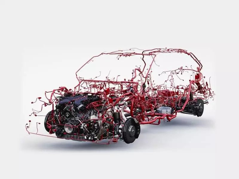
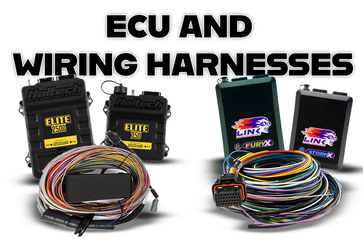
In modern automobiles, the electronic control unit (ECU) plays a crucial role. It is like a “car brain”, real-time reception of sensor signals, control engine injection, ignition timing, emission system, transmission shifting and other key functions. In order to ensure the high-speed, accurate and stable transmission of these control commands, the ECU wiring harness must have high reliability and compatibility.
When constructing or repairing ECU wiring harnesses, an often overlooked but extremely critical technical element is the proper selection of Wire Gauge. The wire gauge not only determines the current carrying capacity of the wire and the quality of signal transmission, but also directly affects the stability, safety and long-term durability of the system. Improper choice of Wire Gauge may lead to signal interference, excessive voltage drop, and even lead to overheating, short-circuiting and other safety hazards.

Overview of ECU Harness
ECU Harness is a set of cable assemblies that supply power and transmit data and control signals to the ECU. It connects the ECU with various types of sensors, actuators, power systems and communication buses to ensure that all signals can still be transmitted accurately, stably and with low interference in complex working environments.
ECU is one of the core components of modern automobile electronic system. It achieves the goals of performance optimization, fuel economy improvement and emission control by controlling the engine and related systems. Taking the engine ECU as an example, it will read data from various sensors in real time, and issue precise commands to multiple subsystems such as fuel injection, ignition, and idle control according to the built-in program logic.
Today, a mid-to-high-end car may be equipped with up to dozens of ECUs, including engine ECUs, transmission ECUs, body control modules (BCMs), ABS control units, ADAS controllers, and so on. These controllers are connected to each other through the wiring harness, constituting a complex vehicle network system, and collaborate to realize the intelligent control of the entire vehicle.
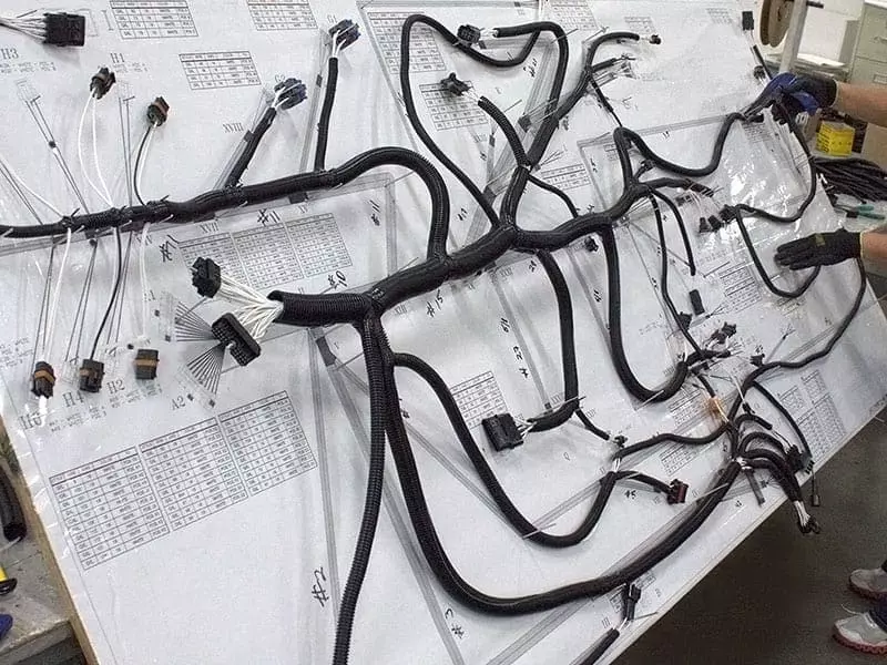
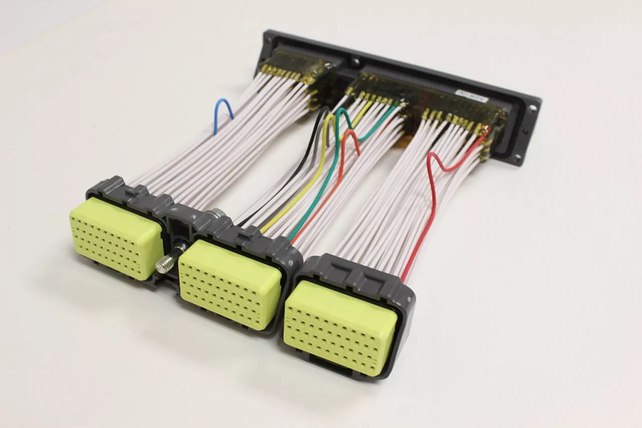
A complete ECU wiring harness usually consists of the following parts:
- Multi-core wires: different colors or markings to transmit signals, power, ground, etc. respectively.
- Connector: connects the ECU end and the sensor and actuator ends.
- Insulation and Protection Layer: Including heat-shrinkable tubing, bellows, waterproof adhesive seals, etc., used to protect against external environments such as oil, water, high temperature and vibration.
- Shielding layer (optional): used to suppress electromagnetic interference, commonly used in CAN, LIN and other high-speed communication lines.
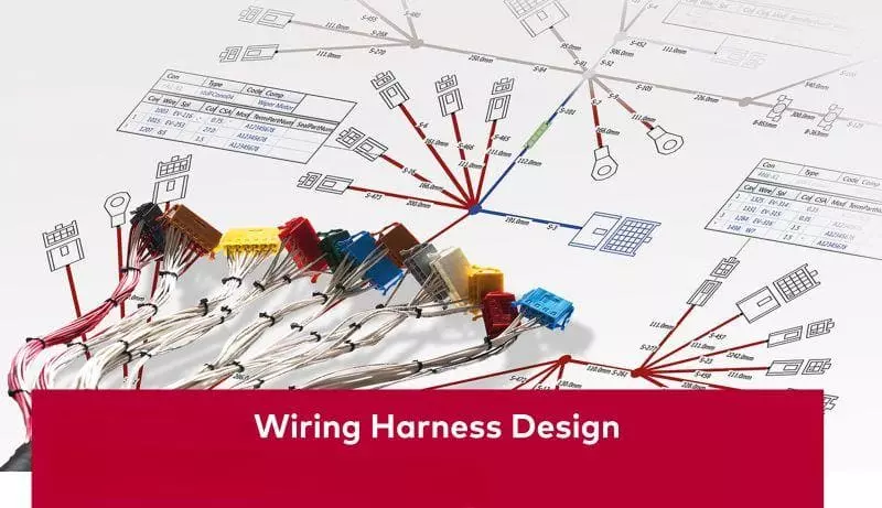
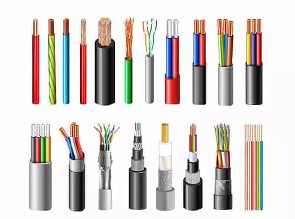
Basics of Wire Gauge
Understanding the concept of “wire gauge” is a critical first step when designing or selecting an ECU wiring harness. Wire gauge does not only regulate the “thickness” of the wire, it directly affects the current carrying capacity, voltage drop, signal integrity and even the flexibility and wiring of the harness. In automotive electronic systems, choosing the right wire gauge is one of the core foundations of signal transmission quality and electrical system safety.
What is a Wire Gauge (AWG)?
Gauge is a measurement used to describe the diameter of a wire. In the United States and most international electrical systems, the AWG (American Wire Gauge) standard is commonly used.The smaller the AWG value, the thicker the wire, the more current it can carry; conversely, the larger the AWG value, the thinner the wire, which is suitable for lower current or signal transmission scenarios.
For example:
- 16 AWG wire is thicker and is suitable for power supply or high load control wires.
- 22 AWG has a thinner wire and is often used for sensor signal lines or data communication lines.
Relationship between AWG and wire performance
| AWG Size | Conductor Diameter (mm) | Cross-sectional Area (mm²) | Typical Current Capacity (12V Automotive Use) | Common Applications |
|---|---|---|---|---|
| 16 AWG | ≈ 1.29 mm | ≈ 1.31 mm² | 15–20 A | ECU main power, relay wiring |
| 18 AWG | ≈ 1.02 mm | ≈ 0.82 mm² | 10–15 A | Ignition, injector control lines |
| 20 AWG | ≈ 0.81 mm | ≈ 0.52 mm² | 5–10 A | General signal control wires |
| 22 AWG | ≈ 0.64 mm | ≈ 0.33 mm² | 0.5–5 A | Sensor signals, CAN/LIN wiring |
Core factors affecting wire gauge selection for ECU harnesses
The choice of wire gauge (AWG) for ECU harnesses is not an arbitrary decision. It requires comprehensive consideration of a number of key factors such as current size, cable length, signal type, thermal environment, mechanical strength, and so on. There are also significant differences in wire gauge requirements for different functions. Below are a few core elements that affect wire selection for ECU harnesses.
1. Current Load
The primary function of a wire is to safely and stably transmit current, so the wire gauge must meet the requirements of the corresponding current load. Too small a wire diameter will easily lead to heat, excessive voltage drop or even fuse; too large a wire diameter will increase the difficulty and cost of wiring.
Actual case:
- Injector control wire: the instantaneous starting current can be up to 2~5A, it is recommended to use 18 AWG.
- ECU main power line: conventional current is about 5~15A, choose 16-18 AWG.
- Oxygen sensor and other signal wires: very low current (usually <0.1A), using 22-24 AWG is more appropriate.
Therefore, the basic method of selecting current-related wire gauges is based on current rating estimation + safety margins + load characteristics (continuous/intermittent).
2. Wire Length and Voltage Drop over Length
The longer the leads, the higher their resistance and the more significant the resulting voltage drop. In low voltage (e.g. 12V) systems, even a 0.5V loss may affect the stable operation of the ECU.
As a professional wiring harness manufacturer, we recommend that thicker gauge wires should be used as a priority when the transmission distance is greater than 1.5 meters to reduce the voltage drop. The table reference is as follows:
| Wire Length (one-way) | Recommended Wire Gauge (for power lines) |
|---|---|
| < 1.5 meters | 18–22 AWG |
| 1.5–3 meters | 16–20 AWG |
| > 3 meters | 14–18 AWG |
If high-precision analog signal transmission is involved, the distributed capacitance of the wire and impedance matching should also be considered.
3. Signal Integrity
As the communication speed of in-vehicle networks increases, high-speed digital buses such as CAN/LIN put higher requirements on wires. Wire gauge selection should not only meet the mechanical and electrical properties, but also with the communication characteristics of impedance matching and electromagnetic compatibility design. For example:
- CAN bus: 20-22 AWG with Shielded Twisted Pair is recommended;
- LIN bus: unshielded single-core wire is allowed, but 22 AWG is still recommended to improve interference immunity;
- Analog signal lines: to prevent coupling interference, it is recommended to use shielded wire or separate alignment.
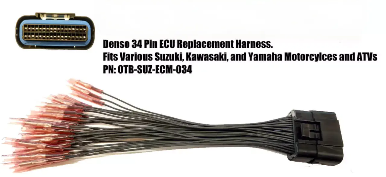
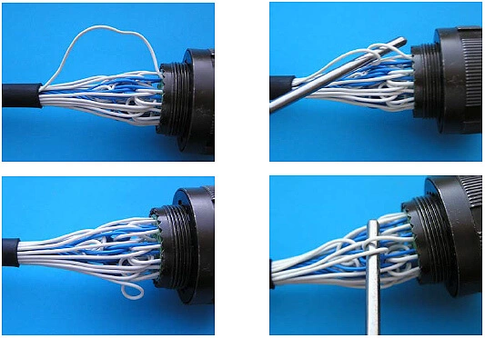
4. Connector Pin Size & Terminal Compatibility
The wire gauge must match the physical dimensions of the connector terminals used. A wire that is too thick may not be inserted into the terminal or may result in a poor crimp; a wire that is too thin may not make stable contact or may come loose due to mechanical vibration. Therefore, before designing the wiring harness, you should synchronize the connector model with the terminal to determine the appropriate wire diameter range, to avoid rework later.
Actual selection experience:
- Delphi, AMP, Sumitomo and other mainstream connector manufacturers provide terminal and wire gauge matching table;
- Some waterproof connectors (such as Delphi GT series) require 18 AWG or more to crimp the seal.
5. Thermal Considerations
ECU wiring harnesses are often laid out in engine compartments, hot zones or near exhaust systems. The ambient temperature directly affects the cable’s current carrying capacity, insulation aging rate and long-term reliability.
- TXL/GXL wires with a temperature resistance of 105°C or higher are recommended for general use in the engine compartment.
- If close to the turbine or exhaust system, high temperature insulation such as Tefzel (ETFE), Cross-link Polyethylene should be used.
- In dense wire harnesses, due to heat accumulation, the wire gauge should be adjusted upwards appropriately to increase the safety margin.
6. Application environment (external influences such as water, oil, vibration, etc.)
Automotive working environments are complex, and ECU wiring harnesses often face physical challenges such as oil, water vapor, dust, high-frequency vibration and pulling. Therefore, in addition to considering electrical properties, attention should also be paid to the impact of wire gauge on mechanical strength and flexibility.
Design Considerations:
- The thicker the wire gauge, the less flexible it is and the more difficult it is to route corners;
- In humid or oily environments, oil-resistant PVC and fluoropolymer insulation should be used in conjunction;
- In areas where the wiring is long and susceptible to vibration, the use of a slightly thicker gauge will help to increase tensile and breakage resistance.
Recommended Wire Gauges for Typical ECU Harnesses
After completing the basic understanding of wire gauge and analyzing the key influencing factors, engineers often need a reference point in actual projects. This can quickly determine the recommended wire gauge range for different wires in various types of ECU harnesses. The following content summarizes typical wire gauge configuration recommendations for common ECU functional wiring based on numerous automotive electrical design examples and industry standards.
These wire gauge choices are widely used in the automotive industry to meet electrical safety and signal integrity, while also taking into account connector compatibility, ease of wiring and cost control.
| Wire Type | Recommended Gauge (AWG) | Application Description |
|---|---|---|
| Signal Wires (Sensors) | 22–24 AWG | Very low current; used for analog or digital signal transmission |
| Control Wires (Actuators) | 18–20 AWG | Controls injectors, ignition coils, etc.; handles moderate current |
| Power Supply Wires | 16–18 AWG | Supplies power to ECU and actuators; requires higher current capacity |
| Ground Wires | 18–20 AWG | Ensures stable return path for signal and power loops |
| Communication Wires (CAN/LIN) | 20–22 AWG | High-frequency data lines; impedance-controlled, often twisted and shielded |
| High Power Control Wires | 14–16 AWG | Drives high-current loads such as cooling fans or solenoids (up to 20A+) |
Recommended Materials and Insulation Types for ECU Harnesses
When selecting wire gauge for ECU harnesses, in addition to focusing on the “thickness” (AWG), it is also important to consider the material of the wires and the type of insulation. These factors will directly affect the durability, safety, anti-interference ability and environmental adaptability of the entire vehicle electrical system.
- Commonly used conductor materials: ECU wiring harnesses commonly use tinned copper conductors, with good electrical conductivity and corrosion resistance. Compared with bare copper, tinned copper is more durable and reliable in humid and high-vibration environments. 2.
- Common Insulation Types: TXL, GXL, Tefzel (ETFE) TXL is suitable for light load scenarios in the car, GXL is more heat and abrasion resistant, and Tefzel is suitable for high temperature and high corrosion environments.
- Recommendations for high temperature / oil resistant applications: GXL or Tefzel insulation is preferred for engine compartments, high temperature or oil contaminated areas. Ordinary PVC insulation is not recommended for such harsh environments and is prone to deterioration or cracking. 4.
- Shielded vs. Unshielded: Shielded wire is recommended for high speed signal lines. Normal power and control lines can be unshielded to reduce costs and wiring difficulties.
FAQs
1. Can I use 18 AWG wire instead of 20 AWG wire?
18 AWG is thicker than 20 AWG, has a higher current carrying capacity, and is generally backward compatible. If space permits, using thicker wire will improve safety margins, but you must ensure that the connector terminals are also compatible with that wire size.
2. Why can't I use too thick wire for ECU sensor wire?
Because the thick wire, although good conductivity, but poor flexibility and wiring difficulties. Sensor signal current is extremely small, with too thick wire is not only unnecessary, but also may affect the connector contact accuracy and shielding effect, but not conducive to system stability.
3. Do all wires in the ECU harness need to be shielded?
No, only communication lines or high sensitivity signal lines need to be shielded. CAN/LIN, crankshaft position sensors, etc. require high interference immunity and shielded twisted pair wires are recommended. Common power lines or low frequency control lines can be unshielded to save cost.
Custom ECU Harness Solutions from Linkwings
The stability and fit of ECU wiring harnesses is critical in modern vehicle and race car tuning. As a Leading custom wire harness manufacturer, Linkwings offers specialized ECU custom wiring harness solutions that can be precisely designed to fit different brands of ECUs, ensuring that every cable meets the electrical loads and installation requirements.
Whether it’s a standard engine management system or a complex multi-module control system, Linkwings can create a clean, reliable wiring harness solution for you. We support custom wire gauges, color coding, connector types, and provide a comprehensive testing process to help you build a stable and efficient power control system.
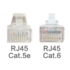
What is the Difference Between Cat5e and Cat6 RJ45 Connectors?
Table of Contents Wh
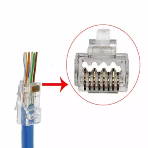
What is RJ45 Connector?
Table of Contents In
Top 10 LVDS Cable Manufacturers in World 2026
Table of Contents In

How to Check Lvds Cable?
Table of Contents In