In the fields of electronic engineering and display technology, the question “What is an LVDS cable?” is being searched by an increasing number of people. LVDS, short for Low Voltage Differential Signaling, is a technology enabling high-speed data transmission via low-voltage differential signals. The LVDS cable serves as the critical medium for this signal transfer. Whether in laptop LCD screens, automotive multimedia systems, industrial equipment, or medical imaging terminals, LVDS cables play an indispensable role.
However, many people’s understanding remains vague: How does it differ from ordinary data cables? Why does it maintain stability during high-speed transmission? Has it been replaced by interfaces like HDMI or DisplayPort? This article will provide a professional, in-depth analysis of the definition, structure, applications, and advantages of LVDS cables, helping you make clearer decisions in project design and procurement.
Fundamentals of LVDS Technology
Before understanding what a LVDS cable is, we must first clarify the meaning of LVDS itself. LVDS stands for Low Voltage Differential Signaling, a technology that transmits data using differential signals. It conveys “0” and “1” by transmitting voltage differences across a pair of wires, rather than relying on the high or low levels of single-ended signals.
The primary advantage of this approach lies in its extremely low voltage requirements (typically around ±350mV) and minimal power consumption. Additionally, since the signals on the two wires are mutually inverted, they effectively cancel out external electromagnetic interference (EMI), significantly enhancing signal integrity.
Compared to traditional single-ended transmission methods like TTL (Transistor-Transistor Logic), LVDS achieves higher data rates at lower voltages. Its transmission speeds typically reach hundreds of Mbps and can even scale to Gbps levels. This is why it is widely used in displays, industrial equipment, and communication systems.
When contrasted with interfaces like HDMI or DisplayPort, LVDS’s characteristics become clearer: it is not a consumer-grade “plug-and-play” standard, but rather a foundational transmission technology. HDMI and DP integrate audio/video protocols and control signals, while LVDS focuses specifically on point-to-point high-speed data transmission. It is particularly well-suited for screen driving, automotive displays, and industrial control applications.
Thus, the core value of LVDS cables lies in their ability to provide stable, efficient high-speed data links for devices—fundamentally distinguishing them from ordinary data cables.
LVDS vs TTL vs HDMI Comparison Chart
| Dimension | LVDS | TTL | HDMI |
|---|---|---|---|
| Signaling | Low-voltage differential | Single-ended | TMDS differential (with protocol) |
| Typical Swing | ±350 mV | 3.3 V / 5 V | ~800 mV (TMDS) |
| Topology | Point-to-point, multi pairs | Point-to-point / bus | Point-to-point (source-sink) |
| Data Rate | Hundreds of Mbps to Gbps | Low–mid (tens of Mbps) | Multi-Gbps (version-dependent) |
| Reach | Usually <10 m (cable/rate dependent) | Short (on-board/in-device) | ~1–15 m (cable/version) |
| EMI Immunity | High (differential/low swing) | Low (noise sensitive) | High (differential + coding) |
| Impedance | ~100 Ω differential | Usually uncontrolled | 100 Ω TMDS differential |
| Shielding | Recommended (twisted/shielded) | Depends on environment | Required, well-shielded |
| Cable Type | Twisted pairs / shielded multi-pair | Single-core/ribbon/FFC | Standard HDMI cable |
| Connectors | I-PEX/Hirose/JST, etc. | Pin header/FFC | HDMI Type A/C/D |
| Protocol Layer | Physical layer only | None | Full A/V protocol stack |
| Typical Use | LCD panels, in-vehicle, industrial | Board-level control/low-speed | TVs, monitors, media devices |
| Cost | Medium (connector/shielding driven) | Low | Medium–High |
| Compatibility | Requires matched Tx/Rx ICs | Simple but noise-limited | Strong, consumer standardized |
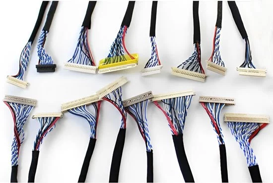
Structure and Composition of LVDS Cable
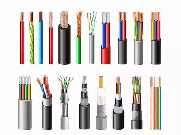
1. Conductor Material
- Copper or tinned copper is commonly used to ensure excellent conductivity and corrosion resistance.
- Tin-plated copper offers superior long-term performance and soldering stability.
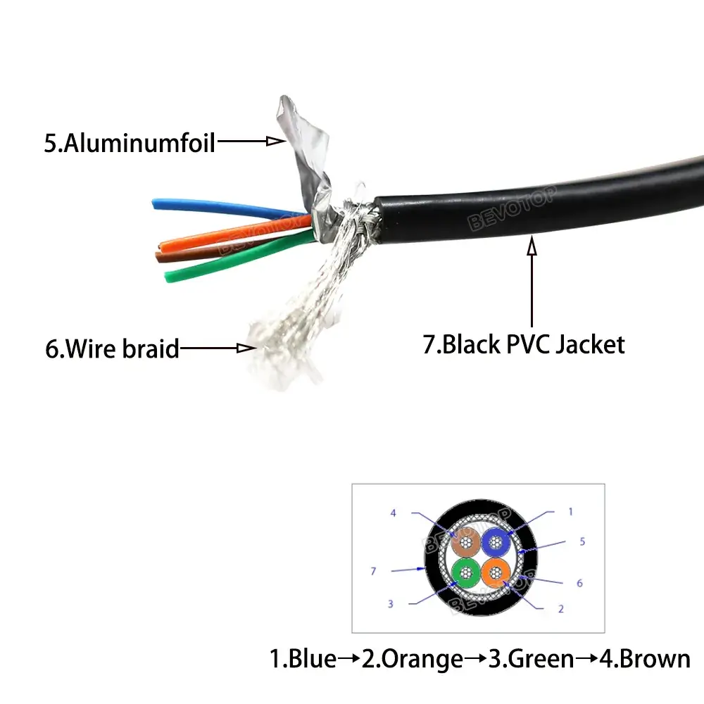
2. Insulation and Shielding
- Insulation Materials: PVC (flexible, low cost), FEP (high-temperature resistance, low dielectric loss), XLPE (high mechanical strength, flame-retardant).
- Multi-layer shielding: Aluminum foil + copper braid combination significantly reduces electromagnetic interference (EMI) and crosstalk.
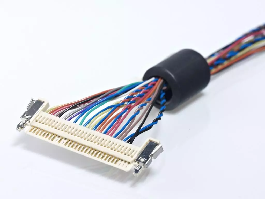
3. Twisted Pair Design
- LVDS signals transmit as differential pairs, necessitating a twisted pair structure.
- Twisted pairs allow interference between signal lines to cancel each other out, maintaining signal integrity.
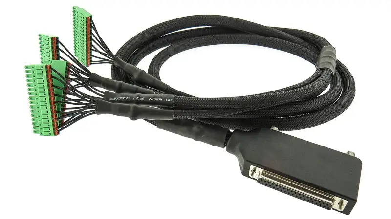
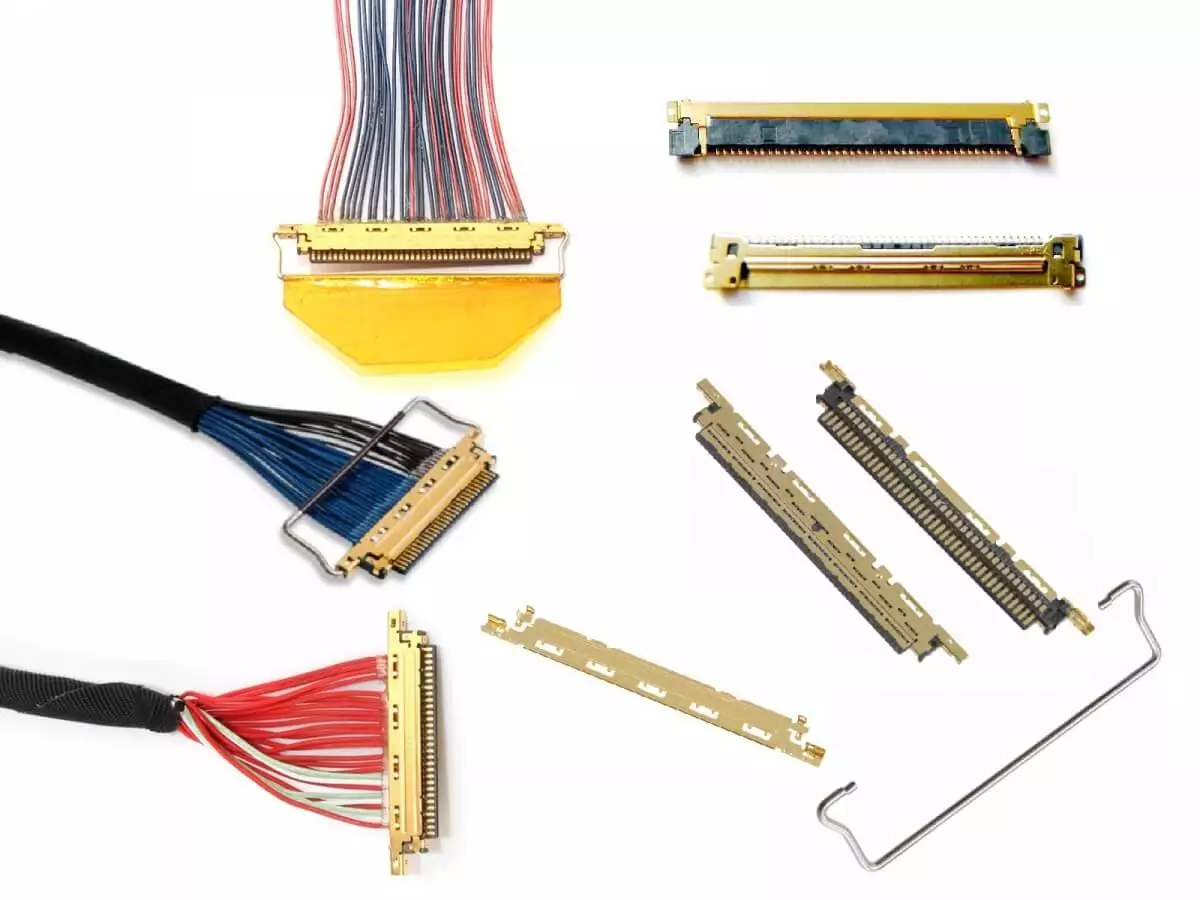
4. Connector Types
- Common interfaces: I-PEX, Hirose, JST, etc.
- Features: High-density design, multiple pins, excellent impedance matching.
5. Typical Characteristics
- Impedance control: Typically 100 Ω differential impedance.
- Low-noise performance: Reduces EMI through differential design and shielding.
- High-speed transmission capability: Stably supports data rates of hundreds of Mbps or even Gbps.
Applications of LVDS Cable
Application 1: Consumer Electronics
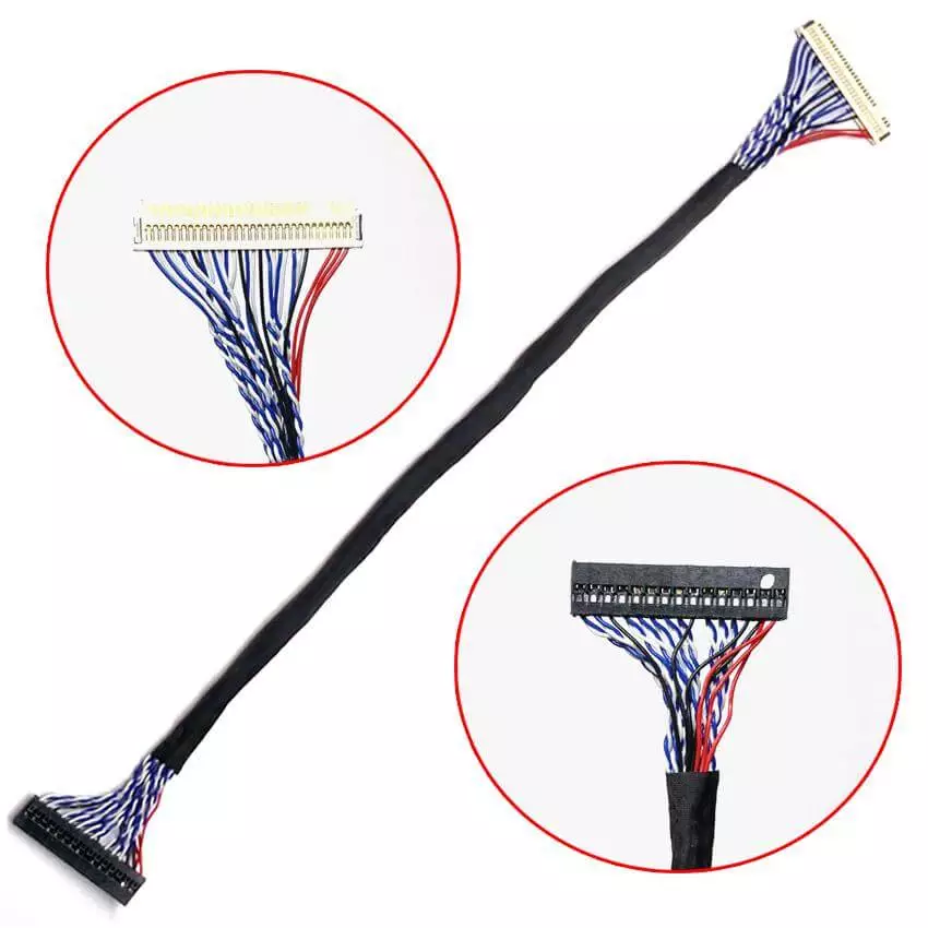
In the consumer electronics sector, the most typical application of LVDS cables is in the liquid crystal displays of laptops and tablets.
LVDS cables are responsible for reliably transmitting high-speed differential signals from the motherboard’s GPU or display controller to the LCD panel. Due to limited internal space within devices, the cables often need to route through hinge areas, necessitating excellent flexibility and bend resistance. The number of LVDS channels increases with resolution and color depth requirements. Common configurations include single-channel or dual-channel LVDS, where each channel comprises multiple differential pairs. Impedance is strictly controlled at 100Ω to ensure high-speed signal integrity.
Common connectors include micro-pitch interfaces such as I-PEX, Hirose, or JST. Additionally, the cables are equipped with shielding layers to reduce electromagnetic interference and prevent mutual interference with modules like Wi-Fi or Bluetooth.
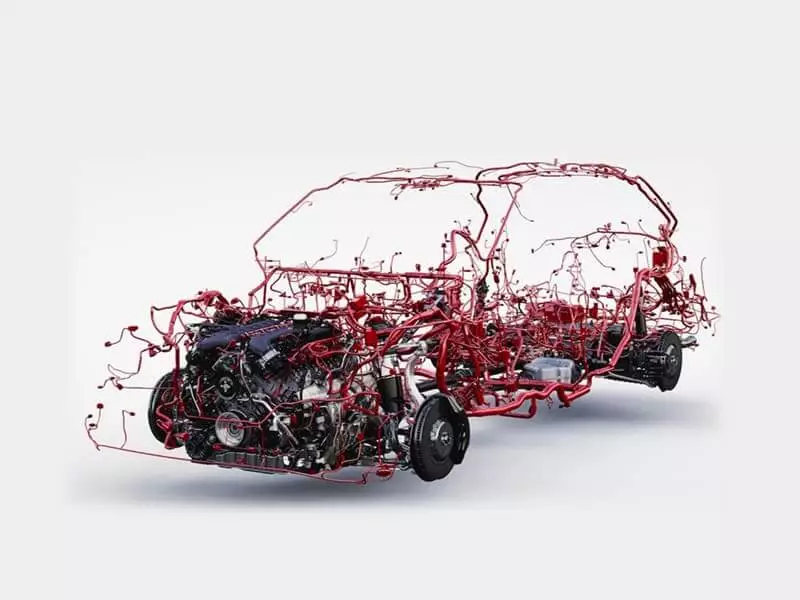
Application 2: Automotive Electronics
In automotive electronics, LVDS cables have become the mainstream choice for in-vehicle display systems, cameras, and infotainment systems.
The wiring environment inside vehicles is complex, featuring long-distance transmission requirements, intense electromagnetic interference, and demanding conditions such as extreme temperatures, vibration, and humidity. LVDS and its evolved technologies (e.g., FPD-Link, GMSL) enable stable transmission of high-definition video. Consequently, they are widely adopted in central control screens, fully digital instrument clusters, panoramic cameras, and rear-seat entertainment displays.
To meet automotive standards, these cables typically employ shielded twisted pair (STP) construction with outer jackets made from high-temperature resistant, oil-resistant, and flame-retardant materials. Shield coverage often exceeds 85% to ensure EMC performance. Connectors emphasize reliability and locking mechanisms to prevent loosening under vibration and prolonged use.
Application 3: Industrial equipment
Industrial equipment represents another critical application domain for LVDS cables. Whether in HMI interfaces within factory automation systems or machine vision inspection equipment, LVDS cables are responsible for transmitting image or control signals in environments with strong electrical interference.
In such scenarios, the cable’s electrical performance must remain stable, while its ability to resist crosstalk and common-mode noise is paramount. Typically employing a composite structure with multiple shielded differential pairs and an outer shield, the outer jacket material is often PUR or TPE to ensure oil resistance, abrasion resistance, and flexibility, making it suitable for repeated movement in drag chain environments. Industrial-grade LVDS cables must also pass certifications such as UL and CSA, and undergo high/low temperature cycling, salt spray, and chemical corrosion resistance testing to ensure long-term stable operation.
Application 4: Medical Imaging
In the medical imaging field, LVDS cables are widely used in high-definition display links for equipment such as ultrasound machines, X-ray machines, CT scanners, and MRI systems.
Medical devices demand extremely high signal integrity, as any delay or noise can compromise image quality. Therefore, LVDS cables must feature strict impedance control and minimal delay skew. To meet these demands, medical-grade LVDS cables typically employ multi-layer shielding and utilize FEP or PTFE as insulation materials to minimize dielectric loss and resist corrosion from disinfectants and cleaning agents. Additionally, to comply with medical electrical standards like IEC 60601, the cables must feature low-smoke, zero-halogen properties and pass rigorous electrical testing alongside a robust quality traceability system.
Advantages and Disadvantages of LVDS Cable
Advantages of LVDS Cable
- High-Speed Transmission Capability: Supports data rates ranging from hundreds of Mbps to Gbps, ideal for high-definition displays and high-speed data links.
- Low Power Consumption: Signal voltage swing is only approximately ±350 mV, resulting in significantly lower power consumption compared to traditional single-ended transmission methods like TTL.
- Strong Interference Resistance: Differential signaling combined with twisted-pair construction effectively cancels electromagnetic interference (EMI), maintaining signal integrity.
- Space-Saving Design: Thin cable diameter makes it suitable for internal wiring in compact devices like laptops and automotive displays.
- Signal Stability: Well-controlled impedance (typically 100 Ω) ensures long-term stable operation.
Disadvantages of LVDS Cable
- Limited transmission distance: Typically less than 10 meters; exceeding this range requires drivers or retimers.
- Requires dedicated interfaces: Depends on LVDS transmitter and receiver chips; does not support universal plug-and-play.
- Incompatible with mainstream interfaces: Cannot directly replace consumer-grade interfaces like HDMI or USB, resulting in relatively limited application scope.
- Partially replaced by newer technologies: Gradually being supplanted by next-generation interfaces such as eDP and MIPI DSI in high-end display applications.
- Cost considerations: Multiple differential pairs + multi-layer shielding + precision connector design make it more expensive than simple signal cables in certain applications.
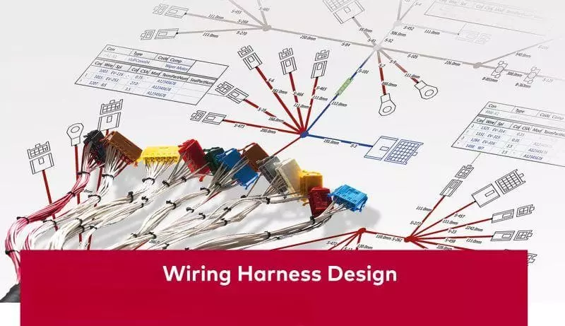
How to Choose the Right LVDS Cable?
1) Application Scenario Requirements
First, derive specifications from the scenario: Determine display resolution/refresh rate or data link bandwidth. Consult the controller/driver chip manual to confirm the required number of differential pairs (e.g., single/dual-channel LVDS, multiple data pairs + clock pairs per channel). Specify cable length and routing path (whether passing through hinges, drag chains, or metal enclosures).
Environmental factors are equally critical: Consumer electronics prioritize flexibility and slim profiles. Automotive applications emphasize high/low temperature endurance, vibration resistance, and robust EMC. Industrial/medical sectors demand long-term stability and resistance to oils/disinfectant chemicals. We recommend reserving 20–30% bandwidth margin after calculations and incorporating structural EMI mitigation (shielding, grounding points, trace isolation) to reduce post-production debugging risks.
2) Electrical Performance Parameters
LVDS is centered on impedance control: the target is 100 Ω differential impedance (typically tolerated at ±10%). Improper impedance leads to reflections and eye diagram collapse. The core of LVDS is impedance control: the target differential impedance is 100 Ω (with a common tolerance of ±10%). Improper impedance leads to reflections and eye diagram collapse.
Focus on intra-pair skew and inter-pair skew to avoid pixel jitter or screen artifacts; match inter-pair lengths as closely as possible, with differential pairs closely parallel or twisted. For EMI/crosstalk control, prioritize the “twisted pair + aluminum foil shield + overall braided shield” structure. Aluminum foil provides nearly 100% coverage; braided shielding should achieve ≥80–85% coverage to enhance low-frequency shielding. For higher data rates or harsh environments, request TDR reports (differential impedance curves) and eye diagram/bit error rate testing (at target speed/cable length conditions). Confirm grounding strategy with suppliers (single-point/dual-end 360° shield termination) to suppress common-mode noise.
3) Mechanical Properties and Structure
Select wire diameter (OD) and conductor gauge (typically 28–32 AWG) based on spatial and motion conditions. Pay attention to minimum bend radius in pivot/bending zones (guideline: static ≥8×OD, dynamic ≥10×OD). Verify bend endurance for drag chain applications. Choose outer jacket material according to environment:
- PVC: General-purpose, cost-effective; moderate temperature and chemical resistance.
- FEP/PTFE: Low dielectric loss, high-temperature and chemical resistance; more expensive.
- XLPE: High mechanical strength, superior temperature resistance/flame retardancy compared to PVC.
- PUR/TPE: Common in industrial/drag chain applications; oil-resistant, abrasion-resistant, cold-resistant.
Structurally, prioritize twisted differential pairs. When necessary, add independent aluminum foil shielding with drain wires per pair, supplemented by overall braided shielding. For high-flex applications, consider ultra-fine stranding and soft insulation to balance flexibility with signal integrity.
4) Certification and Standards
Compliance directly impacts deliverability and market access:
- Environmental/Materials: RoHS, REACH, (where applicable) Halogen-Free/LSZH.
- Flame Retardancy/Safety: Common UL VW-1 flame retardancy requirements for cables; UL 94 may apply to materials in complete units.
- Industry Systems/Testing: Automotive focuses on IATF 16949 systems and CISPR 25/ISO 11452 EMC references. Medical emphasizes IEC 60601-1-2 EMC requirements. Industrial/North American markets may reference applicable UL/CSA standards.
- Traceability: Batch traceability and records of incoming material/process/shipping inspections enhance project credibility and expedite acceptance.
Conclusion: Understanding the Value of LVDS Cables
LVDS cable, as a transmission medium for low-voltage differential signaling, has long played a critical role in notebooks, automotive electronics, industrial equipment, and medical imaging due to its advantages of high speed, low power consumption, and strong interference resistance. Although it is gradually being replaced by new interfaces such as eDP and MIPI DSI in some consumer-grade applications, LVDS remains a mature and reliable choice in scenarios requiring stability and reliability.
For engineers and procurement professionals, understanding its structural characteristics and application boundaries—and selecting appropriate specifications and LVDS wire harness manufacturer based on actual requirements—is essential to fully leverage the value of LVDS cables, achieving a balance between performance, cost, and reliability.
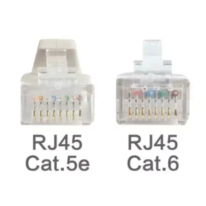
What is the Difference Between Cat5e and Cat6 RJ45 Connectors?
Table of Contents Wh
What is RJ45 Connector?
Table of Contents In

Top 10 LVDS Cable Manufacturers in World 2026
Table of Contents In

How to Check Lvds Cable?
Table of Contents In