What Gauge Wire for Engine Harness? Complete Sizing Guide
Home » What Gauge Wire for Engine Harness? Complete Sizing Guide
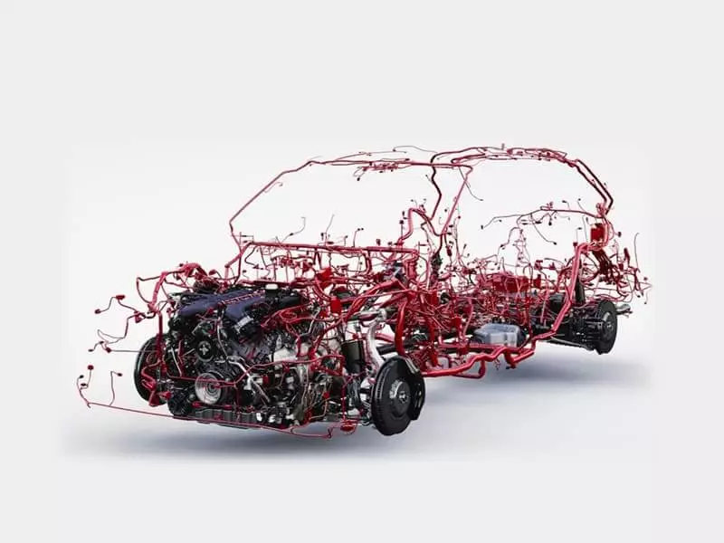
Did you know? When it comes to the wires in an engine wiring harness, “thicker isn’t always better, and thicker isn’t necessarily safer.” If the wires are too thin, they’re prone to overheating and voltage drop. If they’re too thick, they’re heavy, expensive, and difficult to route—and may not even fit into terminals and connectors.
Selecting the right wire gauge isn’t just about the current load; you must ensure sufficient current capacity, account for circuit length and voltage drop, and also consider heat generation, terminal size, and durability.
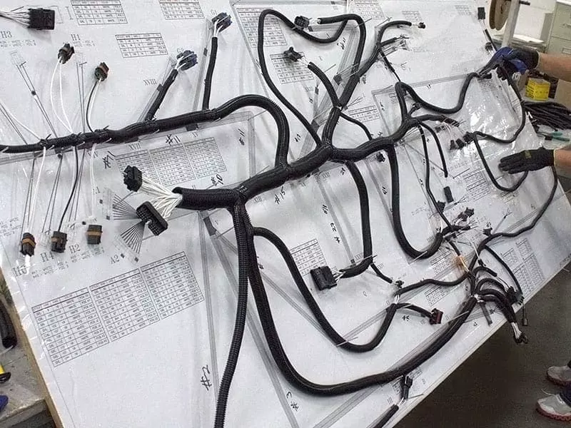
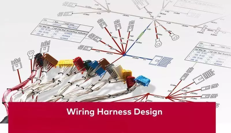
This guide takes a practical approach to wiring harness design and selection, helping you understand common specifications for engine wiring harnesses, the relationship between AWG and cross-sectional area, and methods for quickly matching wire gauge to different circuits.
Is There One Correct Wire Gauge for an Engine Harness?
There is no single, universally correct wire gauge. An engine wiring harness consists of multiple functional circuits, each with different current loads, wire lengths, allowable voltage drops, and terminal specifications. The appropriate wire gauge must be selected individually based on the specific load requirements and installation environment.
The direct answer: size each circuit by load and installation conditions
I. Precise Wiring Based on Actual Load and Interface Limitations
In an engine wiring harness, different circuits perform entirely different functions. It is recommended to determine the wire gauge for each circuit separately based on its actual load and installation conditions.
When designing a wiring harness, do not rely solely on the rated current listed on the equipment nameplate; you must also account for the peak starting current of the motor load. Additionally, when selecting wires, you need to consider the physical compatibility and mechanical strength of the terminals and seals.
When selecting wire gauge, you need to consider the circuit’s actual operating current, potential peak currents, circuit length, allowable voltage drop, and other factors.
II. Dynamic Adjustments Based on Wiring Length and Environmental Heat Dissipation
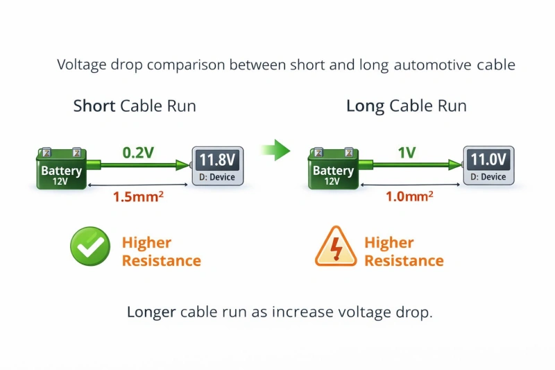
Many people tend to overlook wiring length. The longer the wire, the greater the resistance; longer runs also require thicker wire to control voltage drop. The thermal environment is also critical: high temperatures inside the engine compartment, proximity to exhaust pipes, or wires bundled tightly together can all impair heat dissipation and reduce current-carrying capacity, so sufficient safety margins must be built into the selection process.
Why one gauge can cause voltage drop, heat, or excess bulk
Using a single wire gauge is never the right approach when assembling wiring harnesses in practice.
I. Standardizing the Use of Thin Wires: Voltage Drop and Hidden Overheating Risks
Using wires that are too thin directly increases circuit resistance, creating potential hazards:
- Voltage Drop: High-current devices such as fuel pumps and fans may not receive their rated voltage, leading to reduced speed, difficulty starting, or unstable operation.
- Hidden Overheating: High currents passing through thin wires can cause intense heat; prolonged high temperatures accelerate the aging of insulation and terminals.
Tip: Do not assume that “if the fuse hasn’t blown, the wire gauge is sufficient.” Fuses only protect against short circuits and severe overloads; a circuit can very well operate under severe voltage drops and unreasonable temperature rises for extended periods without blowing a fuse.
II. Using Only Thick Wire: Challenges with Space, Installation, and Compatibility
Although thick wire has lower resistance, using only thick wire can also cause problems:
- Physical Size and Routing: The wiring harness becomes heavy and stiff, making it extremely difficult to bend and route through the confined spaces inside the vehicle.
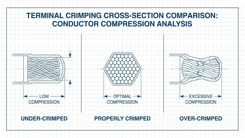
- Terminal and Connector Mismatch: Each terminal has a strict crimping range. If the wire is too thick, the conductor may not fit into the terminal, the crimping wings may fail to close, the sealing plug may not fit, or the terminal may not even fit into the connector housing.
III. How to Select Wiring Harnesses
Comprehensively verify that voltage drop is controllable, temperature rise is reasonable, terminals and seals are perfectly matched, and routing within the vehicle is easy.
- High-load circuits: Focus on calculating current, wiring length, and allowable voltage drop;
- Low-load circuits: After meeting electrical requirements, focus on terminal compatibility, mechanical strength, and routing space.
Which Factors Determine Automotive Wire Size?
The wire gauge of an automotive wiring harness is not determined solely by current. Other factors that must be considered include: preventing the wire from overheating, ensuring that the voltage at the load end does not drop too much, and matching the terminals and fuses, among others.
When selecting the appropriate wire gauge, you should first determine the operating conditions of the circuit before deciding on the conductor cross-sectional area.
Continuous and peak current, duty cycle, and allowable voltage drop
1. Distinguishing Between Continuous Current and Peak Current
When selecting wiring, it is essential to clarify three core metrics:
- Continuous current: The current during stable operation of the equipment, which determines the long-term thermal load on the wire.
- Peak current: The surge current that occurs when motors, fans, and other devices start up or become stalled.
- Duty cycle: The ratio of the time the equipment is powered on to the total operating time. A continuously running water pump and a solenoid valve that activates once every few seconds have different heat dissipation and heat accumulation characteristics.
Tip: Based on our many years of industry experience, we recommend that you clarify the following before selecting wiring: What is the normal operating current? How high is the startup surge current? How many seconds does the high current last? Is the equipment continuously on or does it operate intermittently?
2. Strictly Control Permissible Voltage Drop
In some circuits, wire gauge is increased not out of fear that the wire will burn out, but to maintain voltage.
- Low-voltage systems are extremely sensitive to voltage drops: Since 12V automotive circuits operate at a low voltage, even a 1V drop represents a loss of more than 8% of the total voltage.
- This directly affects equipment performance: Insufficient voltage to the fuel pump can result in inadequate fuel pressure; excessive voltage drops to the ECU or sensors can cause signal drift or even trigger fault codes.
Tip: Do not rely solely on “AWG current-carrying capacity charts” found online. These charts do not account for the length of your wiring or how sensitive your devices are to voltage drops. The current-carrying capacity for each specific circuit must be calculated individually based on the actual wire length and the target allowable voltage drop.
One-way length, return path, ambient temperature, and bundle derating
One-Way Length
When measuring wire length, it is not recommended to measure only the one-way distance from the power source to the device. The actual voltage drop is determined by the entire circuit; if the wiring on the load side is ignored, the calculated voltage drop may be underestimated. When calculating wire length, the total length of both the positive and negative wires must be included.
Current Return Path
Whether using a dedicated negative wire or grounding through the engine block or vehicle body, the gauge of the ground wire, the contact resistance at the grounding point, and the connection terminals are all part of the circuit. If the impedance of the return path is too high, using a thicker positive wire will be of no use.
Ambient Temperature
Even if the insulation jacket is heat-resistant, the wire itself may not be capable of carrying high currents at high temperatures. In extremely hot areas of the engine compartment—such as near the exhaust pipe or turbocharger—heat dissipation is very poor. The temperature rise caused by the wire’s own electrical resistance will compound the heat from these hot zones. When selecting wire specifications, sufficient current rating margin must be allowed; one cannot simply apply the nominal values for room temperature.
Wire Harness Bundling Derating
A single wire suspended in the air dissipates heat well, but when dozens of wires are bundled together and then enclosed in a corrugated tube or braided sleeve, the temperature may rise more rapidly. High-current circuits in main wire harnesses must be derated according to the bundling factor; otherwise, the inner wires may overheat and age prematurely during actual operation.
Terminal capacity, fuse rating, mechanical strength, and future loads
| Factor | What to Check | Practical Guidance |
|---|---|---|
| Terminal Capacity | Wire size, insulation OD, and seal compatibility | If wire size increases, verify the terminal and connector still fit. |
| Fuse Rating | Protect the wire without nuisance blowing | Match the fuse to the load, wire, and terminal capacity. |
| Mechanical Strength | Vibration, bending, pulling, and service stress | Very small wires may fail mechanically even at low current. |
| Future Loads | Planned circuit expansion | Add margin only for known future loads, not vague upgrades. |
| Overall System Fit | Wire, terminal, connector, fuse, and load compatibility | If one part does not match, reassess the whole circuit. |
How Do You Calculate the Required Gauge?
You can break this down into two parts: first, determine whether this wire is “sufficient” from an electrical standpoint, and then confirm whether it “can be used reliably” under the actual installation conditions.
Tip: Don’t just consult an AWG chart to find the answer. Such charts can help you narrow down your options, but they shouldn’t be the sole basis for determining the final wire gauge.
Define the load, current, length, and voltage-drop target
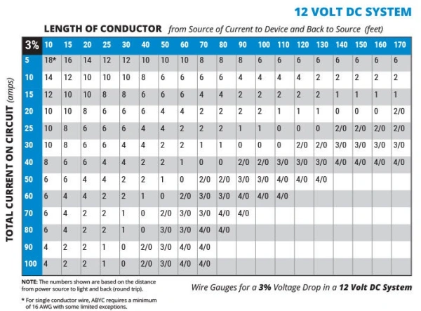
Before designing a circuit, consider the following four basic conditions: load type, operating current, total wiring length, and allowable voltage drop.
Load Type: For sensors and solenoid valves, consider the normal operating current; however, for motor-driven loads such as fans and water pumps, pay attention to the peak current during startup—do not base calculations solely on the steady-state operating current.
Consider the total wiring length: When calculating length, do not measure only the one-way distance from the “power source to the device”; you must also include the length of the return path from the “device to the ground/power source.”
Set voltage drop and resistance limits: Use the basic formula: Vdrop = I × R
You can calculate the maximum allowable resistance threshold for the entire circuit based on the maximum allowable voltage drop: Rmax = Vdrop / I
Match the Cross-Sectional Area by Referring to a Table Based on Wire Specifications
Although the theoretical formula for wire resistance is:
R = ρ × L / A
When actually assembling a wiring harness, do not rigidly memorize and apply fixed AWG resistance constants.
- R is the wire resistance
- ρ (rho) is the material resistivity
- L is the total length of the conductor
- A is the cross-sectional area of the conductor
Select conductor size, apply derating, and verify the terminal and fuse
| Item | Check | Selection Tip |
|---|---|---|
| Conductor Size | Meets continuous current and voltage-drop needs. | Treat it as a candidate size, not the final spec. |
| Derating | Heat, bundling, sleeving, and duty cycle affect cooling. | Recheck ampacity in harsh conditions; avoid fixed derating guesses. |
| Terminal Capacity | Crimp range, insulation OD, seals, and cavity fit. | When wire size increases, verify the terminal and connector too. |
| Terminal Current | Terminal can carry the real load current. | A thicker wire does not make the connection point stronger. |
| Fuse Rating | Protects the circuit without nuisance trips. | Match the fuse with the load, wire, and terminal together. |
| Final Check | Current, voltage drop, heat, terminal, and fuse all pass. | Choose by the whole circuit, not only by an AWG chart. |
Worked example for a fuel-pump or cooling-fan circuit
Four-Step Method for Practical Calculations (Using a 12V/10A Fuel Pump Circuit as an Example)
1. Calculate the total circuit length (round trip):
Power supply wire (one way): 3 m + Separate ground wire (one way): 3 m = Total length: 6 m.
2. Set the target voltage drop and calculate the maximum allowable resistance:
If the maximum allowable voltage drop is Vdrop = 0.5 V, then the maximum allowable total resistance of the circuit is:
Rmax = Vdrop / I
3. Verify candidate wire gauges using a reference table:
Look up the resistance per unit length in the wire data sheet and substitute it into the formula to calculate the actual voltage drop:
Vdrop = Current × Resistance per meter × Total length
If the actual voltage drop > 0.5 V, the wire gauge is too small and must be upgraded to a larger gauge.
4. Closed-loop secondary verification:
After ensuring the voltage drop is within limits, continue to verify: temperature rise under a sustained $10\text{ A}$ current load, heat dissipation adjustments for bundled wires, inrush current during startup, terminal crimping compatibility, and fuse specifications.
What Gauge Ranges Are Common by Circuit Type?
You can estimate a wire gauge range based on the circuit type, but don’t treat “a certain type of equipment = a specific AWG” as a fixed formula.
A reasonable approach is to first identify a candidate range based on the circuit’s function, and then determine the final wire gauge based on the actual current, circuit length, voltage drop, ambient temperature, and terminal specifications.
Low-current sensors, references, communications, and shielded signals
- Low-current sensor circuits: The focus is on ensuring the reliability of terminal crimping and mechanical durability. Since the circuit current is low, the key factor determining the minimum wire gauge is not current-carrying capacity.
- Reference voltage circuits: The focus is on controlling line resistance and contact resistance. Abnormal resistance can directly cause measurement errors in the sensor; therefore, ensuring contact reliability takes priority over current-carrying capacity.
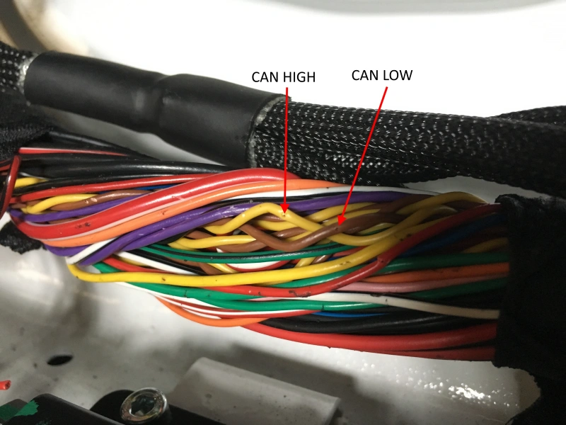
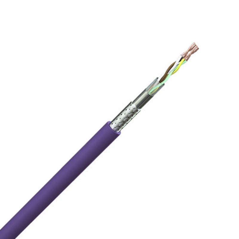
- Communication circuits: For circuits such as CAN bus, the specified twisted-pair structure, characteristic impedance, and topological architecture must be strictly maintained; under no circumstances should thicker wires be used indiscriminately, as this would compromise the cable structure.
- Shielded signal circuits: For signals prone to interference—such as crankshaft, camshaft, and knock signals—use specialized shielded cables or twisted-pair cables that meet the requirements; do not substitute them with ordinary wires.
Injectors, ignition coils, solenoids, relays, and small actuators
- Fuel injectors: Although controlled by ECU signals, they essentially drive electromagnetic loads, and their current is significantly higher than that of sensor circuits. Wire gauge and thermal load must be evaluated based on medium-power circuits.
- Ignition coils: Their low-voltage power supply terminal is classified as a power circuit rather than a signal line; it carries high operating currents—whether momentary or sustained—and requires sufficient current-carrying capacity and voltage drop control.
- Solenoids and small actuators: Wire gauge should not be determined solely based on the term “solenoid.” Drive currents vary greatly; selection must be based on actual operating current, the drive method under PWM control, and thermal load.
- Relays: Distinguish between the coil control circuit and the contact load circuit. The coil circuit carries a relatively low current and can use a thinner wire gauge; the contact load circuit supplies power to equipment such as fans and pumps, so a thicker wire gauge must be selected separately based on the actual high-power load.
- Small Actuators: Evaluation must be based on actual load characteristics. If PWM drive is used, determine the wire gauge based on the switching frequency and thermal load; never treat these circuits as equivalent to signal lines.
Pumps, fans, heaters, charging leads, starter control, and main grounds
| Circuit Type | Typical Wire Size / Feature | Selection Tip |
|---|---|---|
| Fuel Pumps / Cooling Fans | Often 16–10 AWG or larger, depending on power. | Do not size by device name. Check current, inrush, length, and voltage drop. |
| Heaters | Continuous power loads sized by long-term current. | Focus on heat rise, terminals, and connector temperature performance. |
| Charging Leads | May require 8, 6, 4 AWG, or larger. | High current and long runs make voltage drop and joint resistance critical. |
| Starter Control | A control circuit, much smaller than the main starter cable. | Do not use battery-cable sizing just because it controls the starter. |
| Starter Motor Cable | One of the highest-current circuits in the vehicle. | Calculate by cranking current, length, voltage drop, environment, and terminals. |
| Main Ground | Sized by return current and allowed voltage drop. | The ground path must match the high-current supply path; low circuit resistance matters most. |
TXL vs GXL vs SXL Wire: Which Insulation Should You Use?
TXL, GXL, and SXL are all common cross-linked insulated wires used in automotive low-voltage wiring harnesses.
| Type | Relative Insulation Thickness | Best Focus |
|---|---|---|
| TXL | Thinnest | Small OD, lightweight builds, dense harnesses, and tight routing. |
| GXL | Medium | A balanced choice for space, weight, and mechanical protection. |
| SXL | Thicker | Better for circuits needing extra abrasion margin and protection. |
Wall thickness, temperature, abrasion, flexibility, bundle size, and routing
Insulation Wall Thickness:
- SXL has the thickest insulation wall, providing the greatest margin of protection against mechanical damage;
- TXL has the thinnest insulation wall and the smallest overall size;
- GXL falls in the middle, offering a balanced choice that combines protection and compact dimensions.
Abrasion Resistance:
Under identical conditions, the thicker the insulation layer (such as SXL), the greater the margin of mechanical protection it provides against external friction, pinching, and sharp edges. If the harness is exposed to areas with a high risk of friction, this protective margin is particularly critical.
Harness Diameter and Space:
When there are numerous circuits, the thin-wall advantage of TXL becomes evident. A slight reduction in the outer diameter of each wire, when combined, can significantly reduce the overall harness diameter, lower the total weight, and alleviate crowding at the connector ends.
Routing and Protection:
Do not make a blanket decision based solely on the fact that the wiring is “located in the engine compartment.” As long as it is securely fastened, kept away from sharp edges, and protected by a corrugated tube or braided sleeve, TXL is just as reliable.
Temperature Rating:
The letters T/G/SXL do not indicate the level of temperature rating. It is also important to note that a high temperature rating does not equate to unlimited current-carrying capacity; conductor heating, ambient temperature, and temperature rise within the bundle must still be evaluated individually.
Flexibility Characteristics:
Although thin-walled TXL is easy to bend in tight spaces, the actual flexibility of the wire also depends on the number of conductor strands, the diameter of the individual wires, and the insulation material. Do not blindly assume that TXL is more flexible than SXL simply because the insulation is thinner; refer to the specific wire specifications.
Copper versus copper-clad aluminum and why material matters
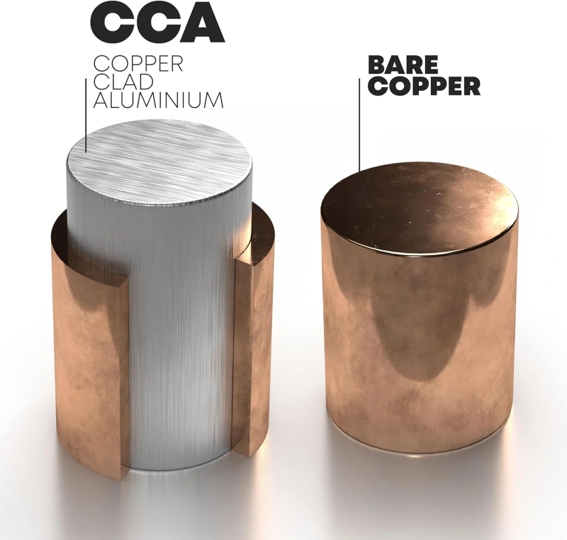
The Key Differences Between Pure Copper and Copper-Clad Aluminum (CCA)
- Fundamental Differences in Material: Bare copper is a pure copper conductor; CCA consists of a thin copper cladding around an aluminum core, with the interior still made of aluminum.
- Differences in Physical and Electrical Properties: Aluminum has lower electrical conductivity than copper. For the same AWG gauge and length, CCA has higher resistance, lower current-carrying capacity, and greater temperature rise.
- Dimension System Does Not Equate to Electrical Performance: AWG represents only a physical dimension system; copper wire and CCA of the same AWG must never be directly interchanged as equivalents.
Why Material Selection Is Critical for Automotive/Engine Wiring Harnesses
- Low-Voltage Systems Are Sensitive to Voltage Drop: Automotive power supply voltages are low; an increase in circuit resistance directly leads to excessive voltage drop, affecting the operation of electronic devices and sensors.
- Terminal Crimping and Connection Reliability: Copper and aluminum differ in mechanical properties and surface characteristics. Using crimp terminals and processes designed specifically for pure copper on CCA can lead to mechanical loosening or increased contact resistance.
- Long-Term Environmental Stability: In the harsh conditions of the engine compartment—such as high temperatures, high vibration, and humidity—aluminum is more prone to electrochemical corrosion and metal fatigue.
How Should Grounds and Power Feeds Be Sized?
The power wire and ground wire form a complete current loop; the gauge of the ground wire must match that of the positive power wire. If only the positive wire is thickened while the ground wire is neglected, excessive resistance in the return path will cause severe voltage drops and system instability.
Shared-return current, engine bonding, voltage drop, and ground loops
| Concept | Core Meaning | Check Point |
|---|---|---|
| Shared-return Current | One ground path carries the combined return current of multiple loads. | Size the wire and ground point by the combined current. |
| Engine Bonding | The engine, body, and battery negative need a low-resistance connection. | Check wire size, crimping, contact surface, fastening, and corrosion protection. |
| Voltage Drop | Both power and ground wires can create voltage loss. | Measure voltage drop on both the positive and ground sides. |
| Ground Loops | Multiple ground paths can cause unwanted current and signal noise. | Separate power ground from signal ground; keep high current away from sensitive references. |
Fuse and relay placement near the power source
1. Fuses
- Primary Function: To interrupt the current in the event of a short circuit or abnormal overcurrent, thereby protecting the downstream wiring.
- Installation Location: Fuses should be installed as close as possible to the power source, such as the battery or power distribution point, in order to minimize the length of unprotected wiring and reduce the risk of short circuits.
- Rating Selection: Must balance wire safety and load characteristics. The fuse rating should exceed the normal continuous operating current, and selection should account for inrush current and time-current characteristics.
2. Relays
- Core Function: Use a low-current control circuit (such as a switch or ECU) to switch a high-current main circuit, preventing high currents from flowing directly through control components.
- Layout Principles: Focus on shortening the high-current path; prioritize assigning longer runs to low-current control wires to reduce system resistance, voltage drop, wire weight, and overall volume.
- Comprehensive Trade-offs: Specific installation locations must be determined in conjunction with the overall power distribution architecture, taking into comprehensive consideration the scope of power protection, harness length, thermal environment, water resistance, and ease of maintenance.
When Should You Use Shielded, Twisted, or Special Cable?
Not all engine wiring harnesses require shielded wires or twisted-pair cables. You need to determine whether the circuit carries signals that are susceptible to interference and whether there are strong sources of interference nearby, such as ignition coils, fuel injectors, motors, relays, or alternators.
Crank, cam, knock, CAN, oxygen-sensor, and high-noise circuits
Crank & Cam Sensors
- Differences in Signal Sensitivity: Although both are critical timing signals, magnetic induction sensors produce weaker signals at low RPMs and are more sensitive to electromagnetic noise than digital signal sensors.
- Wiring and Selection Principles: Give priority to following the explicit requirements of the ECU or sensor manufacturer; if no specifications are provided, use shielded or twisted-pair wiring when signal amplitude is low, cable runs are long, or the wiring is located near high-noise areas.
Knock Sensor
- Protection for Weak Signals: These sensors output weak electrical signals generated by engine vibrations, making them extremely susceptible to electromagnetic interference within the engine compartment; they are highly dependent on shielding.
- Shield Grounding Guidelines: Do not arbitrarily alter the original factory shielding structure or grounding method; follow the specified requirements to avoid grounding both ends, which would create a loop current and introduce interference.
CAN Bus
- Twisted-pair wiring is essential: The differential signal mechanism of CAN-H and CAN-L cancels out noise; the two wires must remain tightly twisted together and must not be separated or replaced with standard, independent parallel wires.
- Prioritize system topology: Shielding is only an optional auxiliary measure; during design, priority should be given to ensuring a twisted-pair structure, impedance matching, termination resistor configuration, and reasonable branch lengths in the topology.
Oxygen Sensor
- Differentiated Treatment and Dedicated Wiring: The circuit structures of narrowband and broadband oxygen sensors differ significantly. Broadband sensors involve complex measurement and control circuits; therefore, use manufacturer-specified wiring and connection standards.
- Isolation of Signals and Heaters: Physically isolate the high-current heater power supply circuit from the sensitive measurement signal lines to prevent interference with sensor readings during high-current switching operations.
High-Noise Circuits
- Identifying High-Noise Sources: The primary circuit of the ignition coil, fuel injector drivers, high-current motors, and PWM-controlled loads are the main sources of interference.
- Physical Isolation Is Better Than Blind Shielding: Compared to applying shielding to the entire cable run, optimizing routing is more efficient and results in a lighter weight. Signal wires should be routed separately from high-current wires, long-distance parallel routing should be avoided, and when overlapping is unavoidable, a large crossing angle should be maintained.
How Do Connectors and Splices Limit Wire Selection?
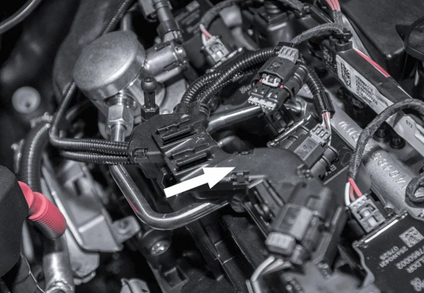
Wiring harness design is a holistic system; the selection of wire gauge cannot be determined solely by current, but must also be perfectly matched to the physical and electrical specifications of connectors, terminals, seals, and splice points. Incompatibility in any single component will render the entire connection system unusable.
Terminal crimp range, seal size, cavity current, pull strength, and serviceability
Terminal Crimp Range
- Strict Specification Matching: Terminals have clearly defined applicable ranges for conductor cross-sectional area and outer diameter of the insulation.
- Avoid Forced Crimping: A conductor that is too thin will result in an insecure crimp, while one that is too thick will prevent the formation of a standard crimp shape.
Seal Size
- Match the finished wire’s outer diameter: The seals in waterproof connectors rely on the wire’s insulation outer diameter to create a seal. A seal that is too small will fail, allowing water ingress; one that is too large will not fit or may crush and damage the seal.
- Be aware of variations in outer diameter among wires of the same gauge: Even for wires of the same AWG gauge, the actual outer diameter may vary depending on the specification or insulation type; actual measurement and evaluation are required.
Cavity Current
- Connector Bottleneck Effect: The system’s maximum current-carrying capacity is limited by the terminal contact area, connector cavities, and internal heat buildup. Using thicker wire does not automatically increase the connector’s current-carrying capacity.
- Multi-Cavity Heat Buildup Assessment: In multi-cavity connectors, multiple high-current terminals operating simultaneously can generate concentrated heat. Conduct a derating assessment based on the actual cavity layout and simultaneous operating loads.
Pull Strength
- Mechanical Connection Stability: Ensure that the connection can withstand long-term engine compartment vibrations, assembly tension, and mechanical stress from removal during maintenance without detaching after crimping.
- Process and Tool Control: Pull strength depends on the compatibility between the conductor and the terminal, the correct crimping depth, qualified crimping tools, and proper crimping procedures.
Serviceability & Splice
- Consider Future Maintenance: Avoid concentrating circuits excessively at overly complex splice points or in deep, hard-to-access areas to reduce troubleshooting and repair costs.
- Wire Gauge Matching at Splice Points: Since a splice consolidates the current from multiple branch circuits, the upstream main line must be reevaluated and sized based on the combined total current—do not simply use the wire gauge of a single branch circuit; downstream branch circuits should be sized according to their respective loads.
- Splice Reliability Verification: Confirm the splice’s load-bearing capacity and mechanical strength, and ensure adequate protection against vibration, bending, and water ingress.
How Do You Validate a Finished Engine Harness?
1. Conduct a static electrical inspection to verify that the wiring is correct and the insulation is in good condition.
2. Verify the electrical performance and voltage drop specifications under actual live and loaded conditions.
3. Conduct mechanical vibration and thermal environment tests to ensure the reliability of the wiring harness under long-term harsh operating conditions.
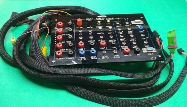
Continuity, resistance, insulation, voltage-drop, thermal, vibration, and load tests
Continuity Test
- Verify Wiring Connections: You need to confirm that each wire is accurately connected to the correct terminal, thoroughly checking for open circuits, incorrect connections, and abnormal short circuits.
- Understand the Limitations of Testing: Do not assume that passing a continuity test means everything is fine. Even if a circuit is conductive, it may still hide issues such as poor crimping or loose terminals; while it may appear normal under a weak test current, problems will immediately surface once the circuit is under actual load.
Resistance Test
- Identify Abnormally High Resistance Points: You don’t need to strive for unrealistic fixed resistance values; instead, consider your harness length, conductor specifications, and number of connectors to precisely identify locations with unreasonably high resistance.
- Focus on High-Current Circuits: We recommend prioritizing the main power supply, main ground, starter, and high-load circuits, carefully inspecting the contact resistance between terminals and ground points.
Insulation Test
- Identify leakage paths: You need to ensure there are no abnormal leakage paths between individual circuits, as well as between wires and the vehicle body ground or shielding layers.
- Strictly control test voltage to protect sensitive components: Do not blindly use high voltage for insulation testing. When dealing with harnesses already connected to ECUs or sensors, strictly follow specifications to select a safe voltage to prevent high voltage from directly damaging fragile electronic modules.
Voltage-Drop Test
Real-world dynamic measurement: You must actually power on the load and run it—this is a critical step that cannot be replaced by static measurements.
Segmented troubleshooting of positive and negative terminals: You should measure the voltage drop separately for “power supply positive to load positive” and “load negative to power supply negative.” Only by doing so can you immediately identify whether the voltage drop bottleneck lies on the power supply side or the ground side.
Thermal Test
- Detect Localized Overheating: You need to let the circuit operate continuously under high current; you must never conclude the test prematurely just because it “doesn’t feel hot” to the touch.
- Pinpoint Fault Locations: You must pay close attention to terminals, connectors, and splices. If you find that the temperature of a terminal is significantly higher than that of the wire itself, experience shows that this is usually not due to insufficient wire gauge but rather to excessive contact resistance.
Vibration Test
- Verifying Mechanical Fatigue Resistance: You must confirm that, under the intense vibrations of the engine compartment, terminals do not come loose, connector latches do not fail, and splices do not experience tensile stress.
- Eliminating Wear and Stress Concentration: You should carefully inspect the wiring harness routing and mounting points to ensure wires do not rub against sharp edges or brackets, and to prevent fatigue fractures in any section of wire caused by repeated bending.
Load Test
- Full-load in-system verification: Actual loads (or equivalent simulated loads), such as fans, fuel pumps, and ignition systems, must be put into operation to comprehensively test the system under real operating currents.
- Capturing Dynamic Surges: When dealing with motor-type loads, it is essential not only to observe performance during steady-state operation but also to closely monitor the high-current surges that occur at startup. Check for terminal voltage drops, ground potential rise, and temperature increases in fuse holders and relays.
Documentation needed for OEM, motorsport, and service builds
| Application | Recommended Documents | Main Purpose |
|---|---|---|
| OEM Production | Schematics, connector pinouts, wire specs, BOM, terminals, splice map, grounds, fuse/relay layout, process specs, inspection standards, test records, revisions, and traceability data. | Keep production consistent, traceable, and controlled during engineering changes. |
| Motorsport | Schematics, ECU pinout, connector IDs, wire list, branch layout, power/ground map, fuse/relay layout, sensor/actuator interfaces, test records, and spare parts list. | Support fast troubleshooting, part replacement, and field repair at the track. |
| Service / Repair | Factory wiring diagram, modified diagram, change list, connector pinout, wire color and gauge, added fuses/relays, grounds, splice locations, terminals, and test results. | Help future technicians understand modifications and locate faults quickly. |
| All Projects | Document version, date, owner, part numbers, test results, change reason, and final status. | Avoid mismatch between drawings and hardware, and support maintenance and traceability. |
Frequently Asked Questions
Q1: Is 18 AWG suitable for every sensor circuit?
No, it is not. 18 AWG is too thick for many sensors; thinner wires are often used for low-current sensors, reference voltages, and communication lines. The final decision should be based on the sensor current, cable length, terminal crimping range, mechanical strength, and whether shielding or twisted-pair requirements apply, rather than using 18 AWG uniformly.
Q2: Should the ground wire be the same gauge as the power wire?
The ground wire is not required to be the same AWG as the positive wire; instead, it should be calculated independently based on the actual return current it carries, the path length, and the allowable voltage drop.
Q3: Can a larger wire gauge cause problems at a connector?
Yes. A wire that is too thick may exceed the crimping range of the terminals, the dimensions of the seals, or the capacity of the connector cavities, leading to poor crimping, assembly difficulties, or seal failure. Therefore, verify that the terminals and connectors are compatible before increasing the wire gauge.
Q4: How much voltage drop is acceptable in a 12-volt engine circuit?
There is no fixed value that applies to all circuits. The allowable voltage drop depends on the load type, line length, and equipment requirements. Sensitive circuits, such as sensors and ECU power supplies, have stricter requirements, while power circuits, such as fans and pumps, may have different acceptable ranges.
Conclusion: What Gauge Wire for Engine Harness? Complete Sizing Guide
In summary, selecting the correct wire gauge for engine harnesses is not a “one-size-fits-all” process; it determines the system’s power supply efficiency, signal accuracy, and operational safety.
A harness is not merely a physical connection—it is the “neural network” that ensures the vehicle’s high-reliability operation. To create a high-performance harness, one must move beyond empirical approaches and comprehensively consider factors such as wire material, terminal crimping, sealing and protection, thermal management, and interference-resistant routing.
As a trusted professional wiring harness and connection solutions supplier , Linkwings relies on rigorous engineering standards and data validation to provide end-to-end support—from scientific selection to custom integration—ensuring that every circuit safeguards peak performance.

Nicole
The founder of Linkwings Electronics.
10+ Years Experience | 1000+ Global Projects Completed
Specialized in:
- Custom Wire Harness Assembly
- Automotive & Industrial Cable Harness Manufacturing
- Precision Crimping & Terminal Processing
- OEM / ODM Wire Harness Solutions
Need help with your project?
Let Linkwingselec deliver your next wire harness solution.