How to Install a Trailer Wiring Harness Safely
Home » How to Install a Trailer Wiring Harness Safely
How to Install a Trailer Wiring Harness Safely and Durably? Verify that the pin specifications of the wiring harness match the electrical connectors on both the tow vehicle and the trailer. When routing the wires, run them along the chassis to minimize contact with high-temperature components and sharp metal edges. Ensure all connectors and exposed terminals are properly waterproofed to prevent rainwater and road de-icing salt from seeping in and causing electrochemical corrosion. After installation, test each light on the trailer one by one.
This article provides a detailed guide on how to safely install a trailer wiring harness.
What are the steps to install a trailer wiring harness?
Step 1: Confirm the Vehicle and Trailer Wiring Harness Specifications
Confirm the following three points:
1. What is the vehicle model, year, and configuration?
- The taillight circuit design may vary by vehicle
- Some vehicles can use a dedicated plug-in wiring harness directly
- Some vehicles require power to be drawn from the taillight wiring
2. What type of trailer plug is used?
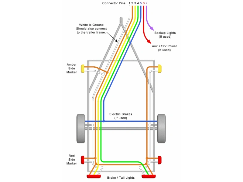
4-pin and 7-pin trailer plugs are different. The former is used for taillights, brake lights, turn signals, and ground. The latter includes basic lighting functions and may also include circuits for electric brakes, auxiliary power, reverse lights, and more.
3. Does the vehicle require a towing module or adapter?
If a vehicle uses a complex body control system, the towing wire cannot simply be connected in parallel with the taillight circuit. In this case, a dedicated towing wiring harness or electronic conversion module is required to minimize lighting malfunctions, CAN bus alerts, or damage to the vehicle’s control module.
Step 2: Prepare Installation Tools and Materials
Recommended items:
- Towing wiring harness compatible with your vehicle model
- Towing plug
- Multimeter
- Wire strippers
- Crimping pliers
- Heat-shrink tubing or waterproof wire connectors
- Electrical tape
- Cable ties
- Socket wrenches/screwdrivers
- Wire pull tool
- Waterproof sealant or wiring harness seals (depending on the installation location)
Tip: Based on years of professional experience, we do not recommend relying solely on standard electrical tape to wrap exposed connections. The underside of a vehicle is prone to exposure to rain, mud, salt spray, and vibration; it is best to use reliable mechanical connections and waterproof protection at wiring points.
Step 3: Disconnect the Vehicle’s Power Supply
Before installation, turn off the ignition and disconnect the negative battery terminal as specified in the vehicle’s service manual.This reduces the risk of short circuits, blown fuses, damage to electrical components, and sparking during the procedure.
If your vehicle is equipped with complex electronic systems, do not disconnect the battery without first consulting the vehicle’s service manual.
Step 4: Locate the Taillight Wiring
After removing the interior trim panel or taillight assembly, you will see the taillight wiring harness. At this point, do not rely solely on wire colors to determine their functions.
This is because wire colors may vary from vehicle to vehicle; even within the same vehicle model, there may be differences based on model year, market version, or trim level. The correct approach is to refer to the vehicle’s wiring diagram and use a multimeter to verify the actual function of each wire.
Step 5: Identify the Function of Each Trailer Wire
Trailer wiring harnesses follow industry-standard color codes: white for ground, brown for taillights, yellow for left turn signal/brake, green for right turn signal/ brake, blue for power brakes, and black for auxiliary power. However, wire color definitions may vary depending on the plug type (e.g., 4-pin, 7-pin round, 7-pin RV blade-style), and the wire colors on the vehicle end and the trailer end may also differ. Therefore, relying solely on color is not accurate.
The correct method is to connect the vehicle and then use a multimeter or a trailer wiring harness tester to test the voltage output of each wire individually while performing operations such as turning on the lights, signaling a turn, applying the brakes, and shifting into reverse to determine their corresponding functions.
Step 6: Connecting the Vehicle and Trailer Wiring Harnesses
When connecting the vehicle and trailer wiring harnesses, select the appropriate connection method based on the type of harness. For dedicated plug-in harnesses, prioritize connecting the plug to the corresponding original vehicle connector according to the manufacturer’s instructions.
For universal harnesses that need to be connected to the taillight circuit, strictly follow the procedure: “Verify the circuit → Strip the insulation → Connect the wires → Apply insulation and waterproofing.”
Tip: After completion, connections must meet the following requirements: secure conductor contact, no exposed copper wires, resistance to pulling and disconnection, and adequate insulation and protection. Ensure the connection is as watertight as possible.
Step 7: Installing the Ground Wire
Improper grounding is a common cause of trailer lighting malfunctions. The ground wire should be connected to a reliable ground point on the vehicle’s body—not simply secured to just any screw.
Recommended grounding locations:
- Reliably connected to the vehicle’s metal body
- Clean contact surface
- No severe rust
- Securely fastened
- Protected from water and dirt
Improper grounding is a common cause of trailer lighting malfunctions. The ground wire should be connected to a reliable ground point on the vehicle’s body—not simply secured to just any screw.
Recommended grounding locations:
- Reliably connected to the vehicle’s metal body
- Clean contact surface
- No severe rust
- Securely fastened
- Protected from water and dirt
Step 8: Route the Wiring Harness from Inside the Vehicle to the Trailer Plug Location
Next, you’ll need to route the wiring harness to the trailer plug mounting location at the rear of the vehicle.
When routing the wiring harness, be careful to avoid:
- Proximity to the exhaust pipe
- Contact with high-temperature components
- Proximity to the driveshaft
- Proximity to the wheel’s range of motion
- Being pinched by suspension components
- Prolonged friction against sharp metal edges
Step 9: Secure the Wiring Harness
Once the wiring harness is routed, secure it using zip ties or fasteners designed for the vehicle. Do not pull the wiring harness too tightly when securing it. Allow for adequate flexibility and movement, especially near the trailer plug.
Step 10: Install the Trailer Plug
Connect the wiring harness to the corresponding trailer plug. During installation, pay attention to pin numbers, plug orientation, wiring functions, and the sealing structure. It is best to install the plug in a secure location that is protected from impact and convenient for connecting to a trailer.
Step 11: Perform Electrical Testing
Do not drive immediately after installation. You must first conduct a test using a trailer light tester or by connecting to an actual trailer. Turn on the vehicle’s parking lights to confirm that the trailer’s taillights illuminate properly. Turn on the left turn signal to confirm that the trailer’s left turn signal flashes properly. Confirm that the right turn signal flashes properly. Press the brake pedal to confirm that the trailer’s brake lights function correctly.
Tip: If using a 7-pin system, you must also check the following based on the vehicle and trailer configuration:
- Reverse lights
- Electric brake signal
- Auxiliary power
- Other control circuits
Step 12: Perform a Final Safety Check
The final step is to inspect the entire installation system. Pay special attention to whether any wiring harnesses are loose, whether any connectors are exposed, whether there is a risk of short circuits, and whether any wiring harnesses are too close to the exhaust pipe.
Tip: If you notice that fuses keep blowing, wiring harnesses are overheating, lights are malfunctioning, or the vehicle displays an electrical fault warning, do not continue using the vehicle. Disconnect the power and inspect the wiring.
Choose the correct vehicle-side and trailer-side harness
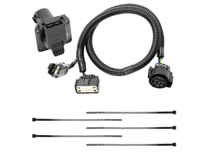
To install a trailer wiring harness, you must first select the correct harnesses for both the vehicle and the trailer.
1. Identify the vehicle-side connector
First, check whether the rear of the vehicle has a factory-installed trailer connector. If a factory connector is present, prioritize using a dedicated wiring harness that matches the vehicle model, year, and trim level. If no factory connector is available, use a universal wiring harness or one with an adapter module to tap into the taillight circuit. When selecting a harness, carefully verify the vehicle model, year, body style, and the model number of the original connector.
2. Confirm the Trailer-Side Plug Type
Check the specifications of the trailer plug. A 4-pin plug supports basic lighting functions such as taillights, left and right turn signals, and ground connection. A 5-pin or 6-pin plug adds functions such as brakes and reverse lights on top of these basics. A 7-pin plug offers the most comprehensive functionality, supporting lighting, brake control, auxiliary power, and more.
3. Verify Compatibility Between Both Sides
When selecting a wiring harness, check the following: whether the connectors match, whether the pin configurations match, whether the voltages match, and whether the load capacities match. If the vehicle side has a factory-specific connector and the trailer side has a standard 7-pin connector, you should use a corresponding adapter harness or conversion kit.
What tools and materials do you need?
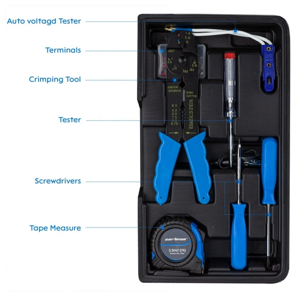
Table 1: Basic Tools Required for Installing a Trailer Wiring Harness
Tool | Primary Use | Notes / Precautions |
Screwdriver Set | Remove interior panels, tail lights, and mounting hardware | Prepare Phillips, flat-head, and other sizes required for the vehicle |
Socket Wrench / Ratchet | Remove and install tail lights, vehicle hardware, and wiring harness mounting bolts | Select the appropriate socket size for the vehicle |
Torx Bit Set (e.g., T25) | Remove Torx fasteners used on certain vehicle models | Select the correct size based on the vehicle’s fasteners |
Torque Screwdriver | Tighten screws to the specified torque | Avoid over-tightening, which may damage components |
Trim Removal Tool / Pry Tool | Remove interior clips and trim panels | Helps reduce damage to trim panels and retaining clips |
Terminal Release Tool | Remove or reposition connector terminals | Must match the connector specification |
Wire Stripper | Strip insulation from electrical wires | Avoid damaging the copper conductors |
Wire Crimper | Crimp electrical terminals and connectors | Use a crimper compatible with the terminal size |
Heat Gun | Shrink heat-shrink tubing | Avoid localized overheating that could damage the wiring harness |
Multimeter / Circuit Tester | Test voltage, continuity, and lighting signals | Do not identify circuit functions based solely on wire color |
Fish Tape / Pull Wire | Guide the wiring harness through narrow or difficult-to-access areas | Select according to the specific routing method |
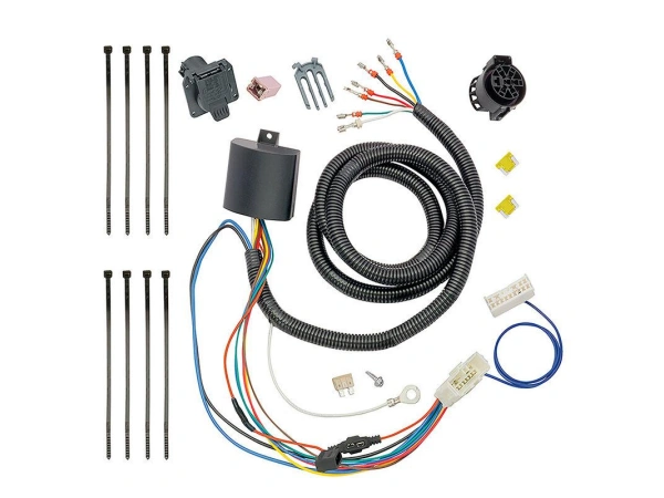
Table 2: Materials and Supplies Required for Installing a Trailer Wiring Harness
Material | Use | Notes |
Trailer Wiring Harness Kit | Connect vehicle and trailer systems | Match vehicle and connector type |
Trailer Socket / Plug | Connect vehicle and trailer | Match connector standard |
Signal Wires | Carry lighting signals | Select proper wire gauge |
Power / Ground / Brake Wires | Provide power, grounding, and brake current | Match current and wire length |
Heat-Shrink Tubing / Butt Connectors | Seal and protect connections | Essential for wet areas |
Electrical Tape | Insulate and bundle wires | Not for waterproofing alone |
Zip Ties / Wiring Clips | Secure the harness | Keep away from heat and moving parts |
Ring / Butt Terminals | Make electrical connections | Match wire size |
Fuse / Fuse Holder | Protect power circuits | Match fuse rating to the circuit |
Circuit Breaker | Protect high-current circuits | Match circuit requirements |
Silicone Sealant | Seal wiring pass-throughs | Use automotive-grade sealant |
Electrical Contact Grease | Reduce moisture and corrosion | Use automotive-grade products |
Wire Loom / Corrugated Conduit | Protect wiring from damage | Recommended for underbody routing |
Plan the cable route before making connections
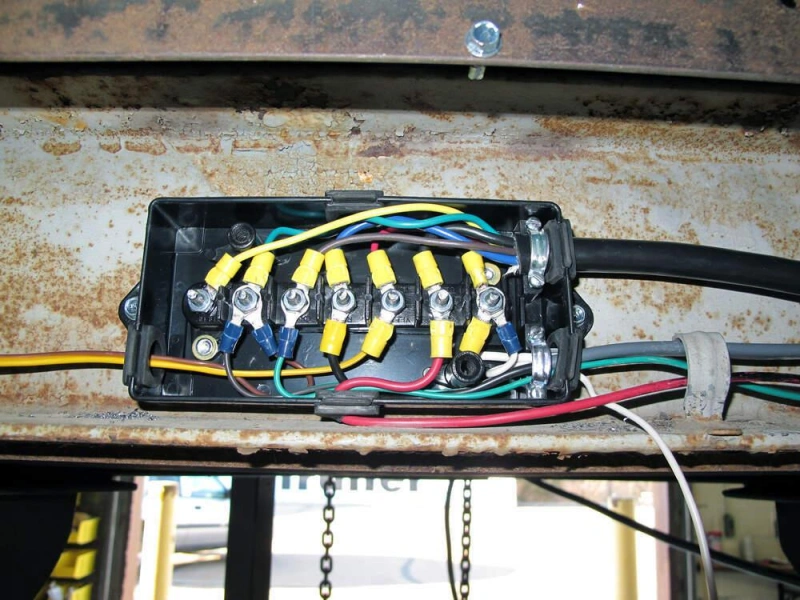
When installing a trailer wiring harness, planning the cable routing in advance is a crucial step.
- Measure the distance
- Use a tape measure to measure the actual distance from the trailer socket installation location to the power source inside the vehicle.
- Allow for 10% to 15% extra length to accommodate bends and sharp turns.
- Choose a routing method
Routing Method | Path | Advantages | Disadvantages | Best For |
Underbody Routing | Along the underside of the vehicle frame from front to rear | Fast installation and good protection | Exposed to road debris; protective conduit is recommended | Most vehicles |
Interior Routing | Through the interior trim from the trunk to the engine bay | Best protection from external damage | More time-consuming; requires removing interior panels | Vehicles used on rough roads or where appearance matters |
Inside-Frame Routing | Through openings inside the frame rails | Highly concealed and well protected from abrasion | Requires suitable frame openings; not possible on all vehicles | Vehicles with built-in wiring openings |
- Avoid Hazardous Areas
- High-temperature areas: Near the exhaust pipe and catalytic converter; maintain a distance of at least 10 cm.
- Moving parts: Areas such as suspension control arms, steering links, and door hinges; cables must be securely fastened and allowed sufficient slack.
- Water-prone areas: The lowest points of the undercarriage and areas prone to submersion when driving through water; connectors must be waterproofed
- Sharp edges: When passing through metal holes, install rubber cable protectors over the openings to prevent long-term vibration from wearing through the insulation
- Wiring Spacing Guidelines
- Straight sections: Secure with a cable tie every 30–40 cm.
- Bends: Add one securing point within 5 cm before and after each bend.
- Near connectors: Place the final securing point 10 cm before the connector to prevent stress on the connector.
- Connector Placement Guidelines
- Do not make connections in locations that are difficult to access for maintenance, such as above the chassis cross members or leaf springs.
- Recommended connection locations: Inside the trunk side panel, near the spare tire well, or other easily accessible locations.
- All connections must use butt connectors + heat-shrink tubing; simply twisting the wires together and wrapping them with electrical tape is prohibited.
- Power Source Planning
- Prioritize drawing power from the fuse box near the trunk (via an auxiliary fuse holder) to avoid running long wires directly from the battery’s positive terminal
- If power must be drawn from the battery, route the power cable entirely through steel conduit or corrugated tubing for protection
- Connect the ground wire to a bare metal bolt on the vehicle body (after sanding off the paint layer); do not screw it directly into a painted surface
Install the vehicle-side wiring
The key to installing a wiring harness on the side of a vehicle is to safely route the vehicle’s original lighting signals and transmit them to the trailer via the trailer wiring harness. However, for models that use a BCM or CAN bus, do not connect the trailer’s load in parallel with the vehicle’s original lighting circuit. Choose the appropriate method based on the vehicle’s design.
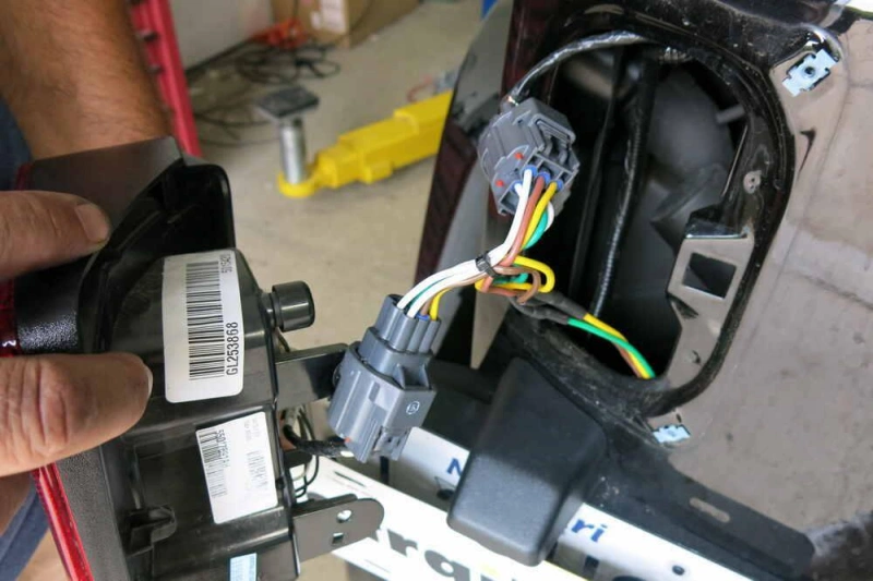
Before proceeding, verify the vehicle’s side connectors, taillight wiring, wiring harness pin assignments, and the specifications of the trailer socket. Once the wiring is connected, secure and protect it.
Connect a powered converter or tow module
If the vehicle’s original lighting system can handle the load of the trailer lights, or if the vehicle’s electronic control architecture is relatively complex, you’ll need to install a converter or trailer module with an independent power supply.
Here’s how it basically works:
Vehicle lighting signals → Converter/trailer module → Independent power supply → Trailer lights
Simply put, the converter identifies the vehicle’s taillight, brake light, and turn signal inputs, then uses its own independent power source to drive the trailer lights, thereby avoiding any additional strain on the vehicle’s original lighting circuit.
Keep the following points in mind during installation:
- Distinguish between the module’s input and output terminals; do not reverse the connection between the vehicle’s side signal wires and the trailer output terminal.
- Wire strictly according to the manufacturer’s pinout; do not rely solely on wire colors to determine function.
- The independent power supply must be sourced from the specified location, and fuses or other overcurrent protection must be installed according to the manufacturer’s requirements.
- Install the module in a dry, secure location that is protected from impact; do not expose it directly to areas under the vehicle where water tends to accumulate.
- If your vehicle uses a CAN bus or BCM control system, be sure to select a module compatible with your vehicle model; otherwise, it may trigger warning lights, generate diagnostic trouble codes, or even interfere with the normal operation of the vehicle’s electronic systems.
Mount the connector and protect the power feed
After connecting the vehicle’s side wiring harness, the next step is to secure the trailer connector in a suitable location at the rear of the vehicle and ensure the power lines are fully protected.
1. Secure the connector. The connector must be mounted on a sturdy bracket or the vehicle’s designated mounting point; it must not be left hanging. The socket should be positioned for easy insertion and removal of the trailer plug and must not interfere with the normal opening and closing of the trunk, bumper, tailgate, or other components.
2. Protect the power lines. If the wiring harness runs from the battery or another power source all the way to the rear of the vehicle, select the correct gauge for the power cables and install a compliant fuse near the power source end of the circuit. The fuse is designed to cut off power immediately in the event of a short circuit or overcurrent.
Tip: If the wiring harness needs to pass through metal holes in the vehicle body, be sure to fit it with a rubber sleeve or suitable cable protector; otherwise, the harness will rub back and forth as the vehicle moves, and the insulation will eventually wear through.
Install the vehicle-side wiring
The key considerations for installing the trailer’s wiring harness differ somewhat from those on the vehicle side. While the vehicle side focuses on signal transmission and power supply, the trailer side places greater emphasis on wire continuity, mechanical fastening, waterproof sealing, and reliable grounding.
Trailers spend long periods on the road, constantly exposed to vibrations, rain, dirt, and temperature fluctuations. If connectors are not crimped securely, seals are inadequate, or the wiring harness is improperly secured, problems are likely to arise after a period of use.
Before installation, organize the functional wires according to the trailer plug’s pinout and plan the routing along the chassis. The wiring harness should be routed as much as possible along the trailer’s existing wire channels or the inner side of the chassis, avoiding the wheels, suspension, exhaust system, and areas prone to mechanical impact.
Make sealed crimps and strain-relieved splices
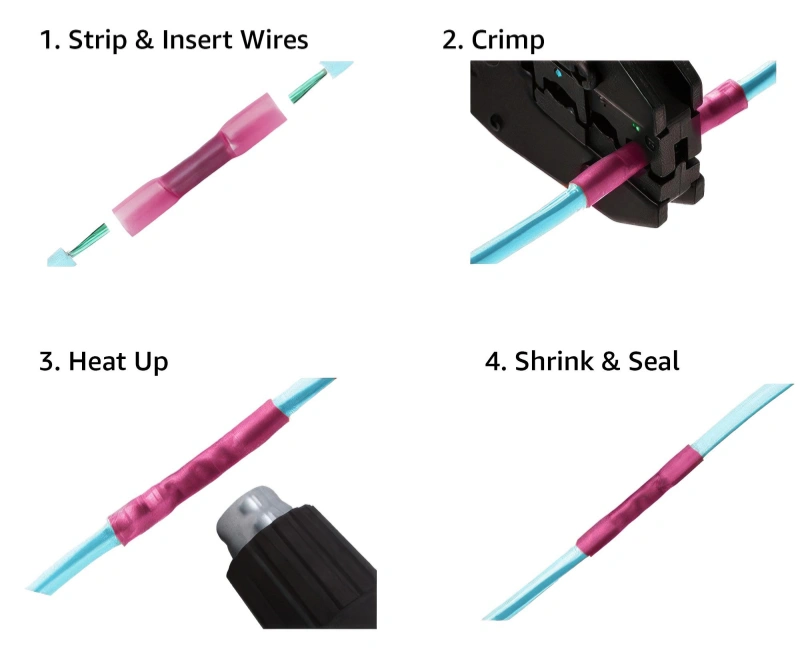
Trailer side connections must not only provide an electrical connection but also withstand the continuous vibrations, tensile forces, and bending stresses generated while the vehicle is in motion. We recommend using waterproof crimp terminals, heat-shrink butt connectors, or certified sealed connectors that match the wire specifications.
Follow this sequence when making the connection:
Step 1: Confirm the wire specifications.
Select an appropriate wire gauge based on the circuit’s actual current and the manufacturer’s requirements, and ensure the crimp terminals match the wire specifications.
Step 2: Strip the insulation to the correct length.
The stripped length should match the terminal; do not strip too much, which would expose the copper core, nor too little, which would result in insufficient crimping length.
Step 3: Crimp correctly.
After fully inserting the wire into the terminal, use appropriate crimping pliers to crimp the connection. After completion, perform a light pull test.
Step 4: Apply Sealing Protection.
If using heat-shrink terminals, use a heat gun to fully shrink the sealing layer, forming continuous moisture protection. For joints exposed on the underside of the vehicle frame, use connection methods with a clearly defined waterproof rating.
Step 5: Set Up Stress Relief.
The joint itself should not be the primary point where the wiring harness bears tension. Appropriate mounting points should be established near the connection so that zip ties, wiring harness clips, or protective sleeves bear the mechanical tension.
Tip: Waterproof sealing and stress relief address two distinct issues. Sealing primarily prevents moisture, salt spray, and contaminants from entering the connection; stress relief prevents repeated tension and vibration from acting on the conductors and terminals. Only by ensuring both are properly implemented can the long-term reliability of the trailer wiring harness be enhanced.
Ground the frame and each high-risk circuit correctly
A reliable ground connection is essential for the proper functioning of a trailer’s lighting system. Although the trailer frame can serve as a common ground point, don’t take this for granted—not all bolts on the frame necessarily conduct electricity well, and factors such as paint, rust, and undercoating can increase contact resistance.
Ground Connection Installation Steps
- Select a location: Choose a sturdy, clean metal grounding point
- Clean: Sand away any paint, rust, or dirt from the surface to ensure the ring terminal makes a tight seal against the metal
- Secure: Tighten the bolt to ensure a stable connection
- Protection: After securing, apply a layer of corrosion protection to prevent future rusting
For trailer lighting systems, it is recommended to establish a clear and reliable common negative/ground path rather than relying on uncertain contact between the light fixture mounting screws and the vehicle frame.
Circuits carrying high currents or requiring independent power supplies—such as auxiliary 12V power sources, electric brakes, and power distribution lines—must be wired separately and grounded according to the manufacturer’s specifications.
After completing the ground connection, use a multimeter to check for continuity between the ground point and the negative terminal of the trailer plug, and verify that there is no abnormal voltage drop when the circuit is under actual load.
How do you test the installation before towing?
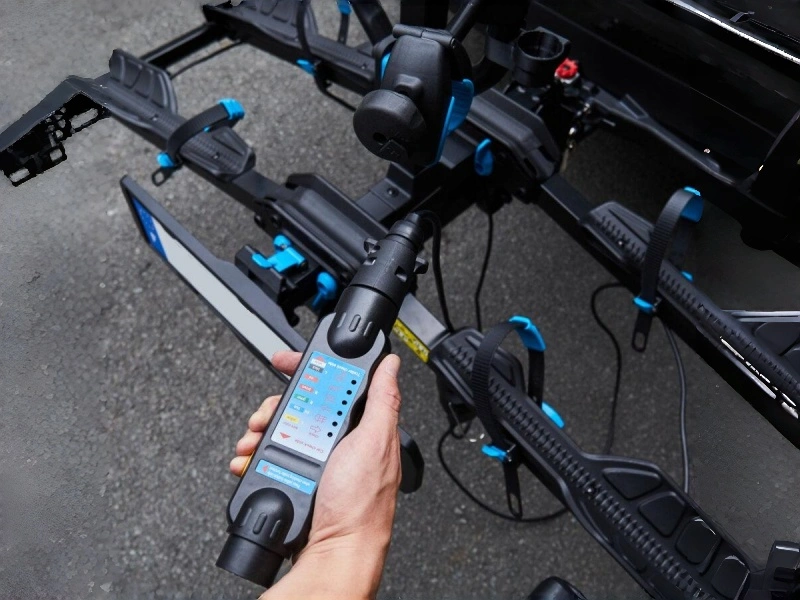
Step 1: Visual Inspection
Before powering on, check the installation:
- Connectors are securely plugged in, terminals are firmly crimped, and heat-shrink tubing is properly fitted
- No exposed copper wires
- Wire harness cable ties are secured in place
- Avoid high-temperature components such as the exhaust pipe, and keep the wiring away from wheels, suspension, and drivetrain components
- Sleeves are installed at wire entry points
- Plugs, fuses, and fuse holders are all properly installed
Step 2: Check the Ground Connection
Use a multimeter to test for continuity between the ground terminal of the trailer plug and the vehicle chassis. Verify that the vehicle’s side ground point is securely fastened, the contact surface is clean, free of rust, and not isolated by paint or coatings.
Step 3: Test Lights and Signals One by One
Connect a trailer or use a dedicated tester to check each function:
- Taillights/Parking Lights: Both sides light up normally
- Left Turn Signal: Flashes normally on the left side
- Right Turn Signal: Flashes normally on the right side
- Brake Lights: Light up normally when the brake is applied
Step 4: Voltage and Wiring Inspection
If a light does not illuminate or the brightness is incorrect, use a multimeter to investigate further:
- Check if the corresponding pin has the correct voltage
- Check if the ground connection is secure
- Check for a voltage difference between the front and rear of the connector
- Check if the voltage across the fuse is normal
- Check for any noticeable voltage drop at the connectors
Step 5: Check the Independent Power Circuit
If an independent power supply module is installed, verify that the power supply path is functioning properly:
Power source → Fuse/circuit breaker protection → Trailer module → Output wiring
The fuse rating must not be too high, the wire gauge must not be too thin, and the power cable must have overcurrent protection. If the fuse blows immediately after powering on, do not simply replace it with a larger one; first investigate the cause of the short circuit or overload.
Step 6: Actual Load Testing
If possible, connect to a vehicle or use a trailer light tester to run a test cycle. Some issues cannot be detected under no-load conditions but only become apparent under load:
- Significant voltage drop
- Connectors overheating
- Dim lights
- Blown fuse
- Module error
Step 7: Check Vehicle Warning Indicators
After installation, check the instrument panel for any lighting malfunctions, trailer module faults, or other abnormal warnings, and verify whether the vehicle’s original lighting system is affected.
If fault codes appear, do not simply clear them and consider the issue resolved; confirm compatibility between the wiring harness, the conversion module, and the vehicle’s electrical system.
Step 8: Final Tug Test and Wiring Inspection
Gently tug on the wiring harness and connectors to ensure they do not come loose easily. Review the following points:
Keep away from high-temperature components → Keep away from moving parts → Do not let the wires drag on the ground → Do not pull the wires too tight → Ensure connectors are properly protected
Common trailer harness installation mistakes
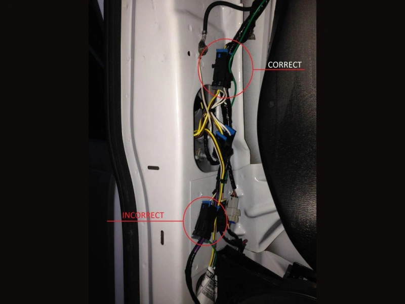
Common Mistake | What Happens | Risk | Correct Approach |
Relying Only on Wire Colors | Connect wires by color without checking the wiring diagram | Incorrect lighting functions | Verify with the wiring diagram, harness guide, and multimeter |
Mismatched Connectors | Connect plugs based only on pin count | Malfunction or short circuit | Check connector type, pinout, voltage, and circuits |
Directly Splicing into Factory Lighting | Connect trailer lights directly to factory circuits | Fuse or BCM faults | Use a vehicle-specific harness or compatible converter |
Poor Grounding | Ground to painted, rusty, or loose surfaces | Dim or flickering lights | Use a clean, secure chassis ground |
No Overcurrent Protection | Power wire lacks a fuse or circuit protection | Wire overheating or fire risk | Install the correct fuse or circuit breaker |
Incorrect Fuse Rating | Use an oversized fuse to prevent blowing | Inadequate circuit protection | Match the fuse to the wire and load |
Undersized Wiring | Use thin wires for high-current circuits | Voltage drop and overheating | Select wire size based on current and length |
Poor Crimping | Loose or incomplete terminal connection | High resistance or intermittent failure | Use the correct terminals and crimping tool |
No Waterproof Protection | Seal underbody connections with tape only | Corrosion and poor contact | Use sealed connectors or heat-shrink terminals |
No Strain Relief | Connector carries the harness weight | Terminal or wire damage | Secure the harness near connections |
Routing Near Exhaust | Wiring is too close to hot components | Insulation damage or short circuit | Reroute and add heat protection if needed |
Contact with Sharp Edges | Wiring passes directly over sharp metal | Insulation wear and short circuit | Use grommets and protective conduit |
Routing Near Moving Parts | Wiring is near wheels or suspension | Pinching or wire breakage | Maintain clearance and secure the harness |
Improper Harness Tension | Wiring is too loose or too tight | Sagging, abrasion, or strain | Leave proper slack and secure it correctly |
Relying on Light Mounting Screws for Grounding | No dedicated ground path | High resistance or light failure | Use a dedicated chassis ground |
Testing Only the Tail Lights | Turn signals and brakes are not tested | Hidden wiring faults | Test every lighting function |
No Load Testing | Only check voltage with a multimeter | Voltage drop or overheating under load | Perform a proper load test |
Ignoring Vehicle Fault Codes | Continue using the system after warnings appear | Electrical or compatibility issues | Check the harness, converter, and load |
No Routing Plan | Decide the cable path after connecting | Excess length or unsafe routing | Plan the full route before installation |
Using an Open Flame on Heat-Shrink Tubing | Heat-shrink is heated with a lighter | Overheating or fire risk | Use a heat gun with controlled heating |
Towing Without Testing | Tow immediately after installation | Brake, turn, or tail light failure | Complete electrical and mechanical checks first |
Frequently asked questions about trailer harness installation
Q1: Can you install trailer wiring without splicing?
A1: Yes. For vehicles equipped with a factory-installed trailer hitch connector, you can use a model-specific, non-invasive plug-and-play wiring harness to connect directly to the vehicle’s original connector without cutting or splicing any wires. For vehicles without a pre-installed connector, you’ll need to tap into the taillight circuit or install an adapter module.
Q2: Should trailer wiring run inside or outside the frame?
A2: Either method is acceptable, depending on the trailer’s structure and protection requirements. Routing the wires inside the frame may offer better protection, but it’s more difficult to install; routing them outside the frame makes maintenance easier, but you’ll need to use protective sleeves and avoid areas exposed to high temperatures, movement, and friction.
Q3: Do LED trailer lights need a converter?
A3: Not necessarily. LED lights have low power consumption, so installing a converter isn’t always required just because LEDs are used. Whether a converter is needed depends primarily on the towing vehicle’s electrical system, the lighting monitoring method, and the compatibility of the trailer module.
Q4: When should installation be handled by a professional?
A4: If the vehicle is equipped with a complex BCM/CAN bus system, requires modifications to the original wiring, the installation of a separate power supply or electric brake control, or if the wiring and pin definitions cannot be confirmed, it is recommended that you have the installation performed by a professional. If any abnormalities occur, you should not continue troubleshooting or using the system on your own.
Conclusion-How to Install a Trailer Wiring Harness Safely
After reading this article, you should now understand how to install a trailer wiring harness safely and reliably. The key to a successful installation lies in verifying the specifications of the wiring harness and connectors, correctly identifying the wires, planning the routing appropriately, ensuring a reliable ground connection, providing adequate waterproofing and mechanical protection, and conducting comprehensive post-installation testing.
However, during the actual installation process, you must select the appropriate wiring harness and connection solution based on the vehicle’s configuration, the type of towing connector, and the electrical system requirements. If you need a reliable towing wiring harness solution, Linkwings offers products that comply with relevant standards as well as customization services. Feel free to contact us anytime!

Nicole
The founder of Linkwings Electronics.
10+ Years Experience | 1000+ Global Projects Completed
Specialized in:
- Custom Wire Harness Assembly
- Automotive & Industrial Cable Harness Manufacturing
- Precision Crimping & Terminal Processing
- OEM / ODM Wire Harness Solutions
Need help with your project?
Let Linkwingselec deliver your next wire harness solution.