JST Connectors: Types, Features and Applications
Home » JST Connectors: Types, Features and Applications
In today’s electronic devices, connectors may be small in size, but they play a crucial role—signal transmission, power connections, and reliable communication between modules all depend on them. Among these, JST connectors are widely used in consumer electronics, automotive electronics, industrial equipment, drones, battery systems, and medical devices due to their compact design, wide range of specifications, and high reliability.
Of course, selecting the right JST connector is also crucial. Factors to consider include the connector series, part number, terminal pitch, number of pins, current-carrying capacity, suitable wire gauge, mounting method, and mechanical locking mechanism.
This article provides a systematic overview of JST connector types, features, and application scenarios to help you understand their basic structure, series naming conventions, and key specifications.
What Are JST Connectors?
JST Connectors are electronic connector products manufactured by J.S.T. Mfg. Co., Ltd. of Japan. Strictly speaking, JST is not a specific model but a connector brand that encompasses an entire product line.
In practical engineering applications, JST connectors are primarily used to establish reliable connections between wire and board, wire and wire, or between other electronic modules.
What parts make up a JST connector?
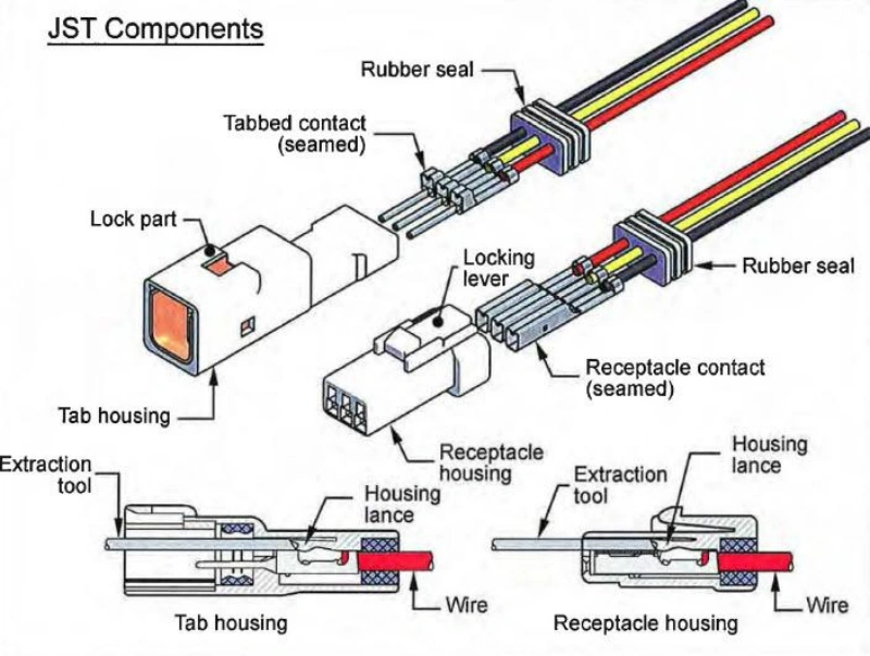
A complete JST connector consists of several key parts:
- Housing (plastic shell): The outer plastic structure of the connector, used to secure the terminals and provide mechanical protection.
- Contact Terminal: The metal conductive part responsible for transmitting current and signals.
Wire Crimp: The point where the terminal connects to the wire, secured through a crimping process. - Header: The male connector mounted on a PCB that mates with the connector at the other end of the wire harness.
Tip: Many people in the market refer to “small white plugs” simply as “JST,” but this is inaccurate. JST is merely the manufacturer’s name, and different JST series are not necessarily compatible with one another. For example, JST PH and JST XH both appear small, but they differ in size, pitch, and terminal structure, so they cannot simply be used interchangeably.
Why Are JST Connectors So Widely Used?
The popularity of JST connectors stems primarily from their perfect balance between size, reliability, and cost.
In space-constrained electronic devices such as drones, robots, 3D printers, and small battery-powered devices, every inch of space on the PCB is at a premium. JST offers a wide range of fine-pitch series that perfectly meet the demands of high-density, miniaturized designs.
Furthermore, JST connectors are almost exclusively crimped to wires. Compared to manual soldering, standardized crimping not only maximizes production efficiency but also reduces errors caused by manual handling. During mass production, the mechanical consistency of the connectors and terminals is crucial for long-term, stable operation.
What scenarios are JST connectors suitable for?
When selecting a JST connector, you should first assess your application requirements; don’t automatically choose JST just because it’s a “small connector.”
Some common applications include:
| Application Area | Common Uses |
|---|---|
| Consumer Electronics | Battery connections, display modules, buttons, LEDs |
| Drones / Model Devices | Battery, motors, control modules |
| Industrial Equipment | Sensors, internal control board connections |
| Automation Equipment | Signal lines, low-power circuits |
| Automotive Electronics | Low-power modules, sensors, internal control unit connections |
If your device has limited internal space and you need to connect sensors or control signals, the compact JST PH, SH, GH, and other similar series may be a good fit.
If you need to connect high-current loads, such as motors or power supply inputs, you should consider larger-sized series rather than choosing a compact JST connector simply because its appearance is similar.
When Are JST Connectors Not Suitable?
1. High-Current Main Power Connections
If the load requires tens of amperes or even higher currents, the standard small JST series may not be the best choice. In such cases, a more suitable high-current connector should be selected based on the actual current, temperature rise, and terminal capacity.
2. High-Frequency, High-Speed Signal Transmission
JST connectors are primarily designed for low-speed signals and power connections. For applications involving high-speed differential signals or high-frequency RF signals, considerations such as impedance control, shielding, and signal integrity requirements must be taken into account.
3. Severe Vibration or Harsh Environments
3. Severe Vibration or Harsh Environments
In environments such as automotive engine compartments or outdoor equipment, it is necessary to verify that the connector has sufficient locking capability, waterproof rating, temperature resistance, and mechanical reliability. Some JST series are not suitable for direct exposure to harsh environments.
How to Read a JST Connector Series and Part Number
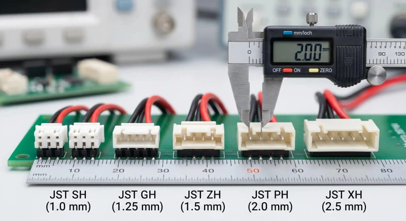
JST is not a single model but an entire ecosystem of connector products. The brand encompasses numerous series—such as PH, XH, SH, ZH, GH, and VH—with each series defined by its specific pitch, terminal structure, applicable wire gauge, and electrical ratings.
To correctly identify a JST connector, one must understand both the “Series” and the “Part Number.”
What do JST series designations represent?
Different series typically correspond to differences in:
- Physical dimensions;
- Pitch (terminal spacing);
- Terminal size;
- Current-carrying capacity;
- Mounting method;
- Application.
| Series | Common Features | Typical Applications |
|---|---|---|
| JST PH | Small size, low power | Batteries, small electronic modules, sensors |
| JST XH | General-purpose connector | PCB connections, control boards |
| JST SH | Ultra-small design | Compact devices, high-density PCBs |
| JST GH | Small pitch, compact structure | Space-limited devices |
| JST VH | Larger size, higher current capability | Power connections, higher-current applications |
Tip: Connectors from different series may look very similar but are not necessarily interchangeable. JST’s product portfolio encompasses a vast array of series and specifications; therefore, identification must be based on the specific model number rather than just the brand name.
Understanding JST Part Numbers
A part number is a code used by the manufacturer to uniquely identify a specific connector component.
A complete JST connection is not just a single part, but a set of mating components:
For example, a wire harness assembly might include:
- Housing
- Contact Terminal
- Header
- Wire
Therefore, when purchasing, you may need to confirm multiple part numbers.
What is the recommended sequence for identifying JST part numbers?
Step 1: Identify the Series
Prioritize identifying the series using the equipment BOM, manufacturer datasheet, PCB silkscreen, supplier documentation, or JST markings. In the absence of such data, measurements of pitch, housing dimensions, pin count, and mating structure can assist in identification; however, note that relying solely on visual appearance carries risks.
Step 2: Identify the Pitch
Pitch refers to the distance between the centers of adjacent pins (common specifications include 1.0mm, 1.25mm, 2.0mm, 2.5mm, etc.). While it is a key criterion for selection, connectors with the same pitch from different manufacturers may still differ in structural design.
Step 3: Identify the Pin Count
Pin count refers to the number of electrical positions on the connector; this affects signal capacity, power and ground distribution, and PCB layout. A single series may offer multiple pin count options.
Step 4: Confirm the Complete Configuration
Finally, compile the full set of specifications, including the brand, series, pitch, pin count, housing part number, terminal part number, PCB header part number, and compatible wire specifications.
Key Specifications: Pitch, Pins, Current, and Wire Size
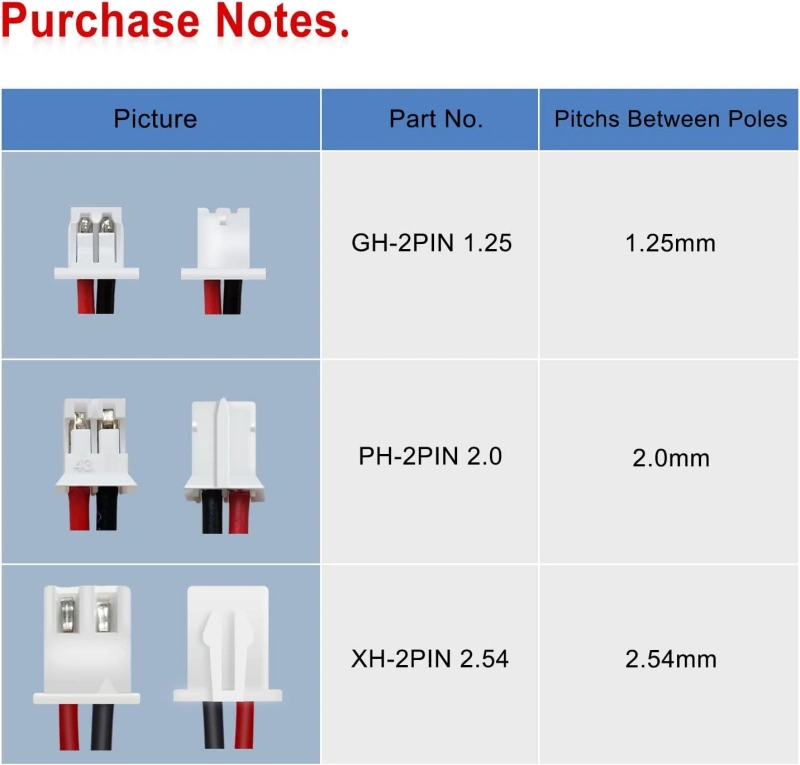
In the actual design and procurement of wire harnesses, connector compatibility is primarily determined by a set of key specifications: pitch, pin count, current rating, and applicable wire size.
These parameters dictate whether the connector can be installed, handle the required current, and establish a reliable connection with the wire harness. If any of these specifications are incorrect, even if the connector physically fits, issues such as poor contact, overheating, terminal damage, or even equipment failure may occur.
| Key Specification | Definition | Main Impact | Selection Guide | Common Mistake |
|---|---|---|---|---|
| Pitch | Distance between adjacent terminal centers, such as 1.0mm, 1.25mm, 2.0mm, or 2.5mm | Affects connector size, PCB layout, and mechanical compatibility | Select based on space, PCB design, and connector family | Assuming the same pitch means full compatibility |
| Pin Count | Number of electrical contact positions, such as 2, 3, or 4 pins | Determines available power and signal connections | Match the actual number of power, ground, and signal lines required | Choosing more pins without considering cost and space |
| Current Rating | Maximum current a connector can safely carry under specified conditions | Affects terminal temperature rise, reliability, and service life | Consider operating current, startup current, duty cycle, temperature, and safety margin | Using only device rated current and ignoring real conditions |
| Wire Size | Supported conductor size, typically specified by AWG or mm² | Affects crimp reliability, current capability, and mechanical strength | Check wire gauge, conductor type, insulation diameter, and terminal range | Checking only AWG without verifying terminal compatibility |
JST PH, XH, SH, ZH, GH, and VH Series Compared
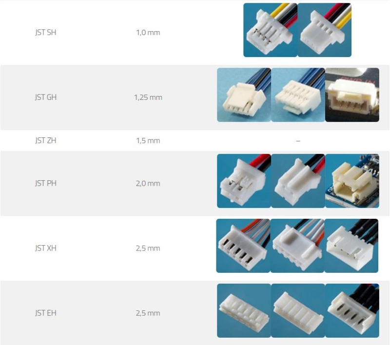
JST connectors are not a single product but rather a connector system comprising multiple series. The primary differences between these series lie in pitch, dimensions, current rating, applicable wire gauge, locking mechanism, and intended application.
When selecting a JST series, you should first clarify the following:
- Whether the connection is for power or signals;
- The amount of available space;
- The required number of pins;
- The operating current;
- Whether the operating environment involves vibration, high temperatures, or frequent mating/unmating cycles.
Do not start by asking “which series is the best”; instead, consider “which series is best suited for the specific application.”
Key Differences Between JST PH, XH, SH, ZH, GH, and VH Series
| Series | Pitch | Key Features | Common Applications | Best Fit |
|---|---|---|---|---|
| JST SH | 1.0mm | Ultra-small, high-density design | Laptops, portable devices, internal signal connections | Very limited space, low-current signals |
| JST GH | 1.25mm | Compact size with locking structure | Industrial devices, small electronic modules | Small size with improved mechanical retention |
| JST ZH | 1.5mm | Compact wire-to-board connector | Small PCBs, sensors | Space-limited, low-power connections |
| JST PH | 2.0mm | Common small connector with wide usage | Batteries, sensors, small devices | General low-power connections |
| JST XH | 2.5mm | Balanced size, current capability, and cost | PCB connections, control boards | General-purpose applications |
| JST VH | 3.96mm | Larger size, higher current capability | Power connections, motors, internal power wiring | Applications requiring higher current capacity |
Other Common JST Series: EH, PA, XA, SM, and RCY
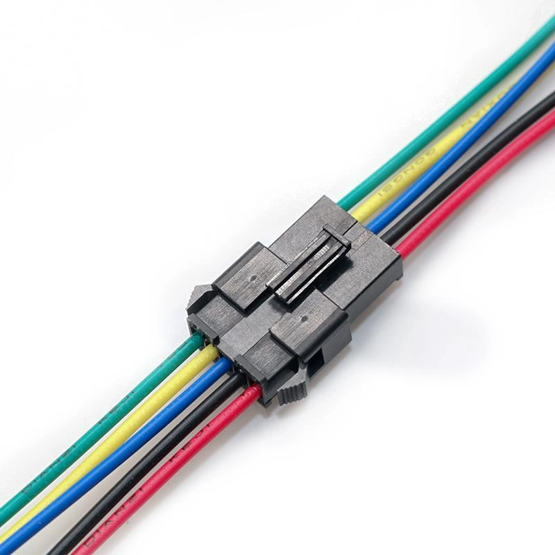
In addition to the PH, XH, SH, ZH, GH, and VH series previously introduced, JST offers other connector series commonly used in specific applications, such as the EH, PA, XA, SM, and RCY series.
These series are widely used in applications including battery systems, remote control equipment, LED lighting, industrial equipment, small motors, and wire-to-wire connections.
Tip: You cannot determine interchangeability between JST series based solely on appearance or pitch; it is essential to verify the complete part number, terminal structure, and application requirements.
Comparison of EH, PA, XA, SM, and RCY Series
| Series | Type | Key Features | Common Applications | Selection Focus |
|---|---|---|---|---|
| EH | Wire-to-Board | Compact, general-purpose design | Small PCBs, control modules, sensors | Space, current, pin count |
| PA | Wire-to-Board | More robust structure | Industrial equipment, control systems | Mechanical reliability, terminal compatibility |
| XA | Wire-to-Board | Locking structure for secure connection | Vibration environments, industrial equipment | Retention strength, vibration resistance |
| SM | Wire-to-Wire | Direct wire harness connection | LEDs, power connections, small devices | Mating cycles, strain relief |
| RCY | Wire-to-Wire | Compact power connection | RC models, batteries, small modules | Current capability, safety margin |
How do you choose between EH, PA, XA, SM, and RCY?
| Decision Question | Selection Direction |
|---|---|
| Connecting to a PCB? | Choose EH / PA / XA series |
| Direct wire-to-wire connection? | Choose SM / RCY series |
| Very limited space? | Prioritize compact series such as EH |
| High vibration environment? | Choose connectors with locking features |
| Connecting battery or power? | Verify Current Rating and Wire Size |
| Frequent maintenance required? | Consider mating reliability and connector durability |
Wire-to-Board, Wire-to-Wire, and Board-to-Board Options
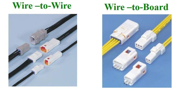
When selecting a JST connector, in addition to considering the series, pitch, pin count, and current rating, it is also necessary to verify the connection type.
Connectors can be categorized into three types based on what they connect:
- Wire-to-Board
- Wire-to-Wire
- Board-to-Board
Wire-to-Board
Definition: Features a wire harness connection at one end and a soldered PCB connection at the other; the PH, XH, SH, ZH, and VH series fall into this category, representing the most common connection method within electronic devices.
Advantages: Wire harnesses can be pre-assembled for direct plug-in, ensuring high mass-production efficiency; damaged modules can be replaced via simple plug-and-play without desoldering; independent design of the PCB and wire harness allows for adaptation to various structural configurations.
Applications: Internal PCB module connections, signal/low-power transmission, and scenarios requiring modular maintenance (e.g., sensors, control boards, battery/motor interfaces).
Not suitable for: Direct wire-to-wire connections or connections involving mechanical parts subject to frequent, wide-angle movement.
Selection criteria: Consider pitch, pin count, rated current, compatible wire gauge, locking mechanism, and mounting orientation.
Wire-to-Wire
Core Definition: Connects wire harnesses at both ends, directly mating two sets of cables without the need for a PCB intermediary. JST series such as SM, RCY, and VL fall into this category.
Key Advantages:
- High modularity: Equipment can be broken down into main harnesses, sub-harnesses, and module harnesses; these are assembled separately and then mated during production. If a module fails, the harness can simply be replaced.
- Suitable for long-distance connections: Offers greater flexibility than PCB connections when modules are far apart, eliminating the need for additional PCB routing.
Typical Applications: Automotive door harnesses, LED module interconnections, battery pack cables, and cable interconnections between devices.
Selection Criteria: Mechanical reliability is prioritized over Wire-to-Board applications because the connector is suspended without PCB support. Key factors include tensile strength, locking retention under vibration, and fool-proofing/reverse-insertion prevention features.
Board-to-Board (BTB)
Core Definition: Two PCBs are mated directly via connectors without the use of wire harnesses. JST’s SHD and JUX series fall into this category; common pitches can be as fine as 0.4mm.
Key Advantages:
- Space-saving: No wire harnesses occupy volume, resulting in cleaner internal routing; ideal for high-density, miniaturized designs.
- Low signal loss: Shortest signal paths make them suitable for high-speed signal transmission—such as internal module connections in mobile phones, cameras, and server daughterboards.
Unsuitable Scenarios: Applications involving relative displacement, significant vibration, or frequent movement between the two PCBs; wire harness connections are more reliable in such cases.
Selection Criteria: Focus on stacking height, pitch, signal transmission rate, and mating cycle durability; also requires fixed PCB positioning and high assembly precision.
Locking, Polarization, and Contact-Retention Features
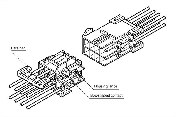
JST connectors incorporate locking, polarization, and contact retention features because these structural elements collectively determine the connector’s reliability during vibration, transport, maintenance, and long-term operation.
Locking Structure: Prevents loosening due to vibration
Core Function: Uses mechanical latches to increase mating retention force, reducing the risk of accidental disconnection caused by pulling forces, vibration, or impact.
Common Types:
- Housing Latches: Integrated plastic latches that lock automatically upon mating; simple and low-cost, suitable for automated mass assembly.
- Active Locking: Features a distinct locking action upon mating and requires pressing a release button to disconnect; offers higher reliability than simple friction retention and is suitable for harsh operating environments.
- Friction Retention: Relies on friction between the terminal and the plastic housing; convenient for mating/unmating but suitable only for static consumer electronics with low vibration levels.
Polarization Structure: Prevents incorrect connection and component burnout
Core Function: Uses mechanical design to restrict insertion to a single orientation, preventing PCB or module burnout caused by reversed power polarity or misconnected signal lines.
Implementation Methods:
- Housing Keying: Asymmetrical protrusions or grooves on the plastic housing physically block insertion if the orientation is incorrect.
- Shrouded Header: A protective frame around the PCB header prevents terminal damage from angled insertion and aids in preventing mis-insertion.
Tip: Poka-yoke (error-proofing) structures cannot completely eliminate human error; connectors with similar appearances in adjacent locations may still be plugged in incorrectly. Engineering solutions such as varying pin counts or using labels can further reduce the probability of errors.
Contact Retention Structure: Prevents terminal back-out
Core Function: Firmly secures the metal terminal within the plastic housing, preventing the terminal from backing out or dislodging during mating/unmating, pulling, or vibration, thereby avoiding intermittent faults like single-pin failure or poor contact.
Failure Risk Scenarios: Axial forces from repeated mating cycles, pulling forces on unsecured wire harnesses, and micro-displacements caused by prolonged vibration can all lead to insufficient retention force and terminal back-out.
Design Key: Most JST series feature an internal locking tab within the plastic housing that snaps the crimped terminal securely into place upon insertion.
How to Choose the Right JST Connector
Selecting the right JST connector is not simply a matter of appearance or choosing a plug that “looks about right.” In actual wire harness design, the connector must meet requirements across four areas: electrical, mechanical, environmental, and manufacturing.
Step 1: Determine the connector application type
- First, identify what the connector is intended to connect, then match it with the appropriate connection method; do not simply search for “JST plug” without context.
- The three application categories and their corresponding scenarios are as follows:
| Application Type | Connection Method | Typical Applications |
|---|---|---|
| Wire-to-Board | Wire to PCB | Control boards, sensors, power modules |
| Wire-to-Wire | Wire to wire harness | LEDs, batteries, small devices |
| Board-to-Board | PCB to PCB | High-density electronic equipment |
Step 2: Confirm electrical requirements
- Rated current: Do not select based solely on the device’s operating current; consider continuous operation duration, peak startup current, ambient temperature, simultaneous current flow across multiple pins, and wire harness heat dissipation conditions.
- Signal vs. power distinction: Signal connections prioritize pin count, space constraints, and contact reliability; power connections prioritize current-carrying capacity, terminal dimensions, and temperature rise performance.
Step 3: Confirm wire gauge compatibility
- Connectors must be compatible with the wire harness; verify wire gauge, conductor material, insulation outer diameter, and terminal specifications—do not rely solely on the connector model number.
- Wire gauge mismatch directly leads to failures: oversized wires cause improper crimping, housing deformation, and insertion difficulties; undersized wires result in insecure crimping and an increased risk of pull-out.
Step 4: Select the series based on space constraints
- Space-constrained scenarios: Prioritize SH, GH, and ZH series; these occupy minimal PCB area, though their fine-pitch terminals are smaller and require higher assembly precision.
- General internal connections: Prioritize PH and XH series; these offer the best balance between size, cost, and manufacturability. High-current scenarios: Prioritize large-specification series (such as the VH series); do not select smaller models simply to achieve a compact profile.
Step 5: Confirm mechanical requirements
- Locking mechanism: Equipment subject to vibration, movement, or long-term operation must feature a locking mechanism to prevent loosening, which could lead to signal loss or equipment downtime.
- Polarity protection (anti-mismatch): In scenarios where incorrect connection could damage the PCB, use connectors with polarity protection (keying/polarization) to prevent damage caused by reversing positive and negative terminals.
- Mating/unmating requirements: For equipment requiring regular maintenance or module replacement, consider the connector’s mating cycle lifespan and ensure there is sufficient operating space.
Step 6: Confirm environmental conditions
- Temperature: High-temperature environments can affect plastic properties and contact reliability; select models with appropriate temperature ratings.
- Vibration: For industrial or mobile equipment, pay close attention to the locking mechanism and terminal retention force to prevent vibration from causing terminal back-out or poor contact.
- Moisture/Contamination: Standard internal PCB connectors are unsuitable for environments exposed to moisture, dust, or chemical contaminants; select models with protective designs.
Crimping, Assembly, and Inspection Best Practices
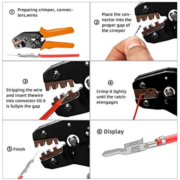
In the production of JST connector wire harnesses, the connector itself is merely one component of the entire system. The reliability of a JST harness depends on the proper execution of the crimping, assembly, and inspection processes.
Tip: The reliability of a crimped connection depends on several factors, including the mechanical bond between the conductor and the terminal, the degree of compression, the deformation state of the terminal, and whether the wire has sustained any damage.
Key Process Points for JST Connector Crimping, Assembly, and Inspection
1. Crimp Process: Ensuring a reliable connection between the wire and the terminal
Core Function: Uses mechanical pressure to wrap the terminal metal around the wire conductor, achieving both electrical and mechanical connection. Crimp quality directly determines wire harness reliability.
Key Crimp Parameters
- Wire Gauge Matching: Terminal must strictly match wire specs. Over-thick wire prevents proper crimping and housing insertion; over-thin wire causes loose crimp and pull-out risk.
- Crimp Height: Height of the terminal crimp zone post-process. Excessive height = under-crimp (poor contact); insufficient height = over-crimp (compromised terminal structural integrity).
- Crimp Tools: Must use specialized crimp tools matched to the specific terminal model. Standard pliers are not acceptable substitutes.
Visual Crimp Standards
- Wire core tip must protrude 0.5–1.0mm, and must not extend into the terminal mating area.
- Both wire core and insulation must be visible in the transition zone between the insulation crimp and core crimp.
2. Assembly Process: Correct installation of terminals into the housing
Terminal Insertion Requirements: After crimping, insert the terminal into the connector housing and verify that the internal locking mechanism is fully engaged; failure to fully lock the terminal can lead to contact issues, loss of power on specific pins, or intermittent faults after insertion into the PCB.
Assembly Verification Points:
- Wire Position: After insertion, confirm that the wire has fully entered the housing and the terminal has reached the designated position; visual inspection alone is insufficient, as some terminals may appear normal but remain unlocked.
- Pin Assignment: For multi-pin connectors, the pin position corresponding to each wire must be verified.
3. Inspection Process: Verifying Wire Harness Manufacturing Quality
- Visual Inspection: Confirm the housing is undamaged and the locking mechanism is intact and undeformed; ensure terminals are fully inserted without backing out or abnormal exposure; and check that wires are free from scratches, abnormal bends, or insulation damage.
- Continuity Test: Verify circuit connectivity according to the design wiring sequence; enables rapid detection of issues such as open circuits, incorrect pin assignments, or poor contact.
- Pull Test: Verify the mechanical bond strength between the wire and the terminal; specific pull-force standards apply based on wire gauge and terminal specifications.
- Crimp Inspection: During production, inspect the crimp appearance, crimp height, terminal positioning, and conductor coverage.
Applications in Consumer, Automotive, Industrial, and Medical Electronics
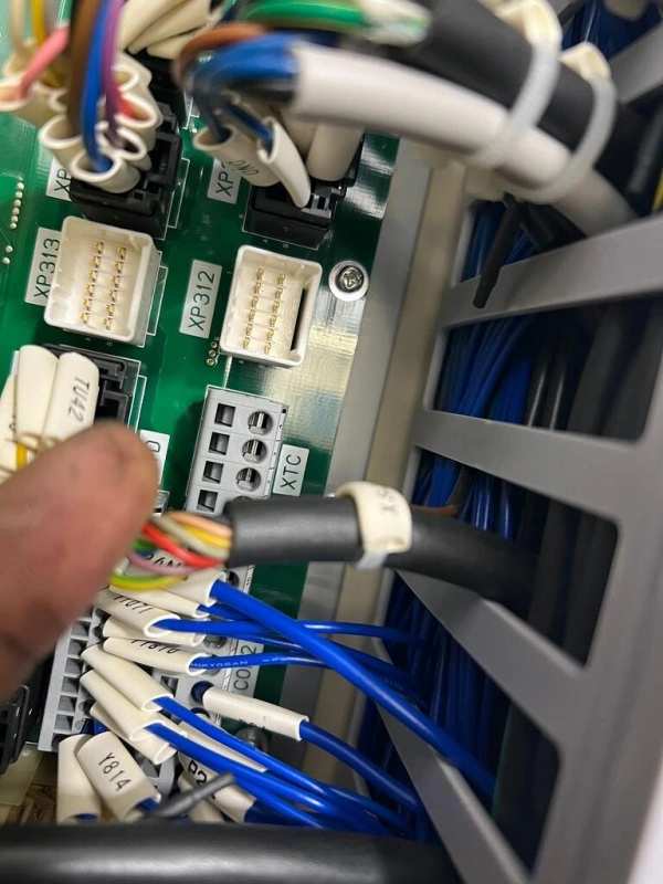
JST connectors are widely used in various electronic devices, yet different application fields have distinct requirements for them.
For example:
- Consumer electronics prioritize miniaturization, cost-effectiveness, and ease of assembly;
- Automotive electronics emphasize resistance to vibration and high temperatures, as well as long-term reliability;
- Industrial equipment focuses on stable operation and ease of maintenance;
- Medical electronics prioritize reliable connections, traceability, and safety standards.
Therefore, when selecting a connector, you should not simply reuse a specific JST series across all products just because it was used previously; instead, you should re-evaluate the choice based on the operating environment, connection functionality, and reliability requirements.
| Application Area | Common Applications | JST Connector Advantages | Key Selection Factors | Common Mistakes |
|---|---|---|---|---|
| Consumer Electronics | Battery connections, LED modules, small sensors, control boards, displays, small motors | Compact size, wide product range, suitable for mass production and easy replacement | Pitch, pin count, wire size, cost, assembly efficiency | Choosing the smallest connector while ignoring strength, assembly difficulty, and reliability |
| Automotive Electronics | Temperature sensors, position sensors, control modules, ECU peripheral modules, small actuators, power connections | Reliable module connections for complex electronic systems | Locking, contact retention, temperature capability, mechanical strength | Using consumer connectors in automotive environments and ignoring vibration, temperature, and lifetime requirements |
| Industrial Electronics | PLC systems, automation equipment, motor control, sensor modules, industrial control boards | Supports modular design, easier assembly, maintenance, and replacement | Locking, terminal retention, wire size, serviceability | Focusing only on initial connection and ignoring long-term operation, maintenance space, and wire harness fixing |
Common Identification and Compatibility Mistakes
When using JST connectors, the most common issue is not a failure to select a part, but rather selecting the wrong model because it looks very similar to the correct one.
JST offers a vast array of product series; while different series may look alike, they differ in terms of pitch, terminals, housings, pin assignments, and electrical ratings.
The correct approach when sourcing, replacing, or designing JST wire harnesses involves ensuring compatibility across four areas:
Mechanical, electrical, wire harness, and application environment.
Nine Common Mistakes in Selecting and Using JST Connectors
| Mistake | Common Misunderstanding | Correct Approach |
|---|---|---|
| Calling every “white connector” JST | JST is a manufacturer name, not a specific connector model. Different JST series have different pitch, terminals, housings, and structures. | Confirm Manufacturer, Series, Pitch, Pin Count, Housing Part Number, and Terminal Part Number. |
| Assuming the same pitch means compatibility | Pitch is only one selection factor. Different series with the same pitch may have different housings, locking structures, and terminals. | Follow the selection order: JST → Series → Pitch → Pin Count → Housing → Terminal. |
| Assuming the same pin count is interchangeable | Pin count only defines the number of contacts, not mechanical or electrical compatibility. | Check Series, Pitch, Housing, and Terminal together. Do not use pin count alone for replacement. |
| Replacing housing without checking terminals | Terminals provide electrical contact, crimping, and mechanical retention. Incorrect terminals can cause poor contact or assembly failure. | Match housing, terminal, and wire as a complete system. |
| Ignoring wire size compatibility | Wire size affects crimp quality, insertion force, current capability, and long-term reliability. | Verify Connector Series, Terminal, Wire Gauge, Insulation Diameter, and Crimp Tool. |
| Ignoring mating direction and orientation | Connectors may differ by Male/Female, Vertical, Right Angle, Top Entry, or Side Entry designs. | Confirm PCB space, mating direction, mounting style, and header type. |
| Ignoring locking and polarization | A connector that fits physically may still lack retention or keying protection. | Use locking connectors for vibration environments and polarized designs for power connections. |
| Choosing only by current rating | Rated current depends on test conditions. Real performance is affected by temperature, duty cycle, and multiple powered pins. | Consider actual operating conditions and keep sufficient current margin. |
| Using third-party “compatible JST” replacements directly | Similar appearance does not guarantee matching dimensions, materials, plating, or mating performance. | Verify mechanical fit, electrical requirements, terminal compatibility, and validate samples before production. |
Frequently asked questions about JST Connectors
Add Your Heading Text Here
Does JST refer to one connector type or a manufacturer?
JST is the name of a manufacturer, not a specific type of connector.
JST (Japan Solderless Terminals) offers multiple series—such as PH, XH, VH, and GH—each with different pitches, structural designs, and terminal specifications. You cannot identify the specific model simply by calling it a “JST plug.”
Are JST PH and JST XH connectors interchangeable?
Generally, they are not directly interchangeable.
Although both JST PH and XH are common wire-to-board connectors, they differ in pitch, housing dimensions, terminal specifications, and current-carrying capacity. You must verify the exact model number; relying solely on the pin count or appearance is insufficient.
What is the difference between 2.0 mm and 2.5 mm JST connectors?
The primary difference is the pitch (the distance between the centers of adjacent pins).
The 2.0 mm and 2.5 mm designations indicate different pin spacings, which affect connector dimensions, terminal design, current capacity, and mounting space requirements. Even if the pitches are similar, they are not necessarily interchangeable.
How can I identify an unknown JST connector?
It is recommended to verify the details in the following order:
- Check for brand markings or part numbers on the connector;
- Measure the pin pitch;
- Confirm the number of positions (pins);
- Examine the housing structure, locking mechanism orientation, and mating style;
- Verify the compatible terminals and wire gauge range.
Do not rely solely on color or general appearance for identification.
Do JST connectors require a special crimping tool?
Using the matching crimping tool is recommended.
JST terminals have specific requirements regarding crimp height, pressure, and positioning. Using standard pliers may result in poor contact, insufficient pull-out strength, or terminal damage. Mass production typically utilizes dedicated crimping machines.
Can pre-crimped JST wires be inserted into any housing?
No.
Pre-crimped wires must match the housing of the corresponding series, including terminal model, orientation, locking mechanism, and wire gauge range. Even if different JST series share the same pitch, they may not be compatible for assembly.
How much current can a JST connector carry?
It depends on the specific series, terminal size, wire gauge, and operating environment. For instance, the compact JST PH series is typically suited for lower-current applications, whereas larger series like the VH can handle higher currents. You cannot determine the current rating based solely on the “JST” name.
Are generic JST-style connectors compatible with genuine JST parts?
Compatibility is not guaranteed.
Many products labeled “JST compatible” or “JST style” may merely resemble the originals in appearance; however, terminal dimensions, tolerances, locking mechanisms, and materials may differ. For high-reliability applications, the use of genuine parts or verified alternatives is recommended.
Conclusion: JST Connectors: Types, Features and Applications
Through this article, you have gained a comprehensive understanding of JST connector types, specifications, and applications—ranging from the basics of series and part number identification to key parameters like pitch, pin count, current rating, and wire size, as well as selection criteria for wire-to-board and wire-to-wire configurations in real-world environments.
As a professional wire harness solutions supplier, Linkwings offers not only JST connector-related harness products but also end-to-end support tailored to your specific application needs—covering everything from connector selection and harness design to sample validation and mass production. If you are looking for reliable JST wire harness solutions, please contact Linkwings; we are ready to help you select the connection solution that best fits your project requirements.

Nicole
The founder of Linkwings Electronics.
10+ Years Experience | 1000+ Global Projects Completed
Specialized in:
- Custom Wire Harness Assembly
- Automotive & Industrial Cable Harness Manufacturing
- Precision Crimping & Terminal Processing
- OEM / ODM Wire Harness Solutions
Need help with your project?
Let Linkwingselec deliver your next wire harness solution.