6 AWG wire: One Wire Size Fits Many Applications
Home » 6 AWG wire: One Wire Size Fits Many Applications
Did you know? 6 AWG wire is one of the most widely used “medium-trunk” wire sizes. Whether it’s powering secondary distribution panels in homes, installing high-wattage electric stoves and central air conditioning units, or running dedicated circuits for the home electric vehicle charging stations that have become increasingly common in recent years, 6 AWG plays a crucial role.
However, in actual selection and installation, factors such as the difference in current-carrying capacity between copper and aluminum conductors, actual performance at different temperature ratings, and the impact of voltage drop on long-distance wiring all affect electrical safety and project compliance.
This guide outlines the core parameters of 6 AWG cable, differences in materials, rules for calculating current-carrying capacity, and selection guidelines to help you make safe and cost-effective decisions during project procurement and installation.
What Is 6 AWG Wire?
Definition and System:
Based on the American Wire Gauge (AWG) standard commonly used in North America, this designation refers solely to conductor size specifications and does not represent a specific type of wire product.
Numbering and Thickness Rules:
The smaller the AWG number, the thicker the conductor. For example, 4 AWG is thicker than 6 AWG, and 6 AWG is thicker than 8 AWG. This goes against many people’s intuition, so it’s easy to make a mistake when selecting wire.
Nominal Cross-Sectional Area:
The corresponding nominal cross-sectional area of the conductor is approximately 13.3 mm². Please note that 13.3 mm² refers to the nominal cross-sectional area of the conductor itself—not the outer diameter of the entire wire, nor the area after insulation is applied.
Material Is Not Specified:
The specification represents only the size and does not specify the material. Both copper and aluminum 6 AWG wires are available on the market, and they differ in electrical conductivity, weight, and current-carrying capacity.
Non-Insulation Type:
This specification does not indicate the type of insulation or jacket. Cables such as THHN, THWN-2, XHHW-2, and NM-B may all use 6 AWG conductors. The label “6 AWG” only specifies the conductor size and does not fully define the wire’s intended application.
Diameter, Cross-Sectional Area, and Metric Equivalent
Diameter
The diameter of a single 6 AWG round solid conductor is approximately 0.1620 inches, which is approximately 4.115 millimeters in metric units. This value represents the conductor diameter based on AWG geometric specifications and does not correspond to the final outer diameter of the finished wire.
Cross-Sectional Area
The nominal cross-sectional area of a 6 AWG conductor is approximately 13.3 mm². Data may vary slightly among manufacturers; for example, TE Connectivity’s AWG conversion table lists approximately 13.25 mm², while Southwire specifies 13.3 mm². Cross-sectional area is a key parameter that determines current-carrying capacity, resistance, and voltage drop.
Metric Equivalent
6 AWG ≠ 16 mm². The nominal cross-sectional area of 6 AWG is approximately 13.3 mm², while 16 mm² is a standard conductor size in the IEC and other metric systems; the cross-sectional areas differ by about 20%. While 16 mm² can be considered one of the common metric specifications closest to 6 AWG, the two cannot be directly substituted for one another.
Solid vs. Stranded Construction
| Comparison | Solid Conductor | Stranded Conductor | Selection Impact |
|---|---|---|---|
| Construction | Single solid metal conductor | Multiple smaller strands | Both can be 6 AWG |
| Flexibility | Lower | Higher | Stranded is better for bends and tight routing |
| Installation | Stiffer and harder to route | Easier to pull and terminate | Stranded suits complex routing |
| Best Use | Fixed installations | Flexible or vibration-prone applications | Choose based on mechanical conditions |
| Conductor Diameter | More predictable | Depends on strand count and construction | Check actual product dimensions |
| Ampacity | Not determined by solid construction alone | Not determined by strand count alone | Material, insulation, and installation also matter |
| Strand Count | Not applicable | More strands generally increase flexibility | More strands do not mean higher ampacity |
| Termination | Check terminal compatibility | Check conductor class and strand type | Fine-stranded wire needs compatible terminals |
| Vibration | Less suitable for repeated movement | Better for vibration and movement | Stranded is preferred in many harness applications |
| High Flexibility | Not intended for high-flex use | Available with fine-strand designs | Do not substitute flexible cable without checking its rating |
| Connector Fit | Check conductor diameter and terminal size | Also check strand structure and crimp method | Same AWG does not guarantee the same terminal fit |
| Procurement | Material, diameter, insulation OD, certification | Material, strand count, construction, OD, certification | Do not order by “6 AWG” alone |
Tip: Aufgrund unserer langjährigen Branchenerfahrung geht es bei der Auswahl nicht einfach darum, zu entscheiden, ob „Solid“ oder „Stranded“ besser ist, sondern darum, ob Ihre Installationsumgebung, die Anforderungen an die Flexibilität, die Kompatibilität der Anschlüsse sowie die konkreten Kabelspezifikationen zueinander passen.
How Many Amps Can 6 AWG Wire Carry?
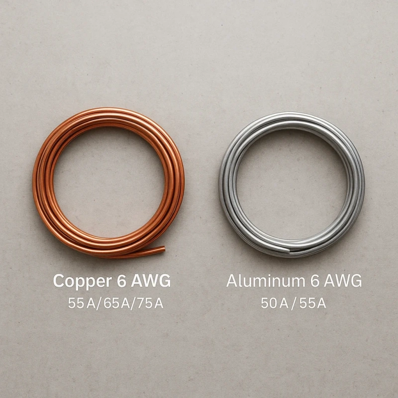
Common answers include 55A, 65A, and 75A, though other numbers may also apply. The reason for this lack of consistency is that ampacity (permissible current-carrying capacity) is not determined solely by the AWG wire gauge.
Ampacity refers to the maximum current a conductor can carry continuously under specified installation and temperature conditions without exceeding the allowable temperature. For the same 6 AWG wire, copper and aluminum have different electrical conductivities, and the insulation and terminals have different temperature ratings, so the corresponding allowable current ratings differ.
Copper Ampacity at 60°C, 75°C, and 90°C
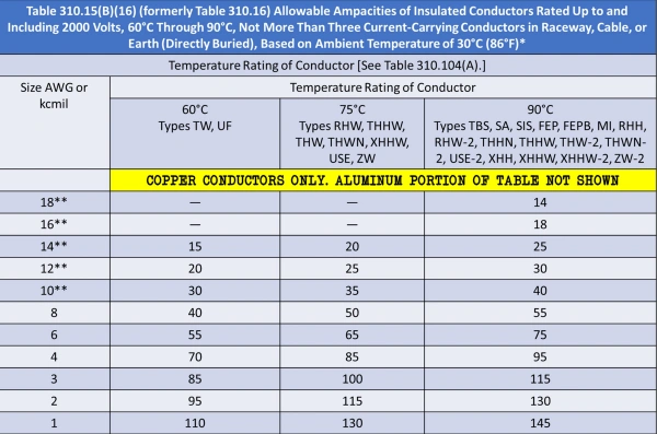
NEC Table 310.16 Current-Carrying Capacity (6 AWG Copper):
60°C: 55A
75°C: 65A
90°C: 75A
Reason for the Differences in Values:
The wire gauge has not changed; the difference lies in the operating temperature allowed by the insulation system. When current generates heat, the higher the temperature the insulation can withstand, the higher the rated current allowed by the table.
Common Misconception:
Having a 90°C insulation rating does not mean you can directly apply the values from the 90°C column (75A). According to NEC 110.14(C), the final current-carrying capacity of a circuit is limited by the terminal temperature rating of the equipment or circuit breaker at either end. If the terminal rating is only 75°C, the calculation must be based on the 75°C column (65A).
Three-Step Method for Actual Selection:
1. Check the wire insulation: Confirm the wire type (e.g., THHN, XHHW-2, etc.) and its corresponding maximum temperature rating.
2. Check the terminal rating: Verify the temperature rating of the switches, circuit breakers, and equipment terminals (e.g., 60°C or 75°C), and use the lower of the two—the wire or the terminal—to determine the base current-carrying capacity.
3. Consider the environment and derating: If the environment is high-temperature or multiple current-carrying conductors are installed in the same conduit, derating must be applied.
Aluminum Ampacity at 60°C, 75°C, and 90°C
NEC Table 310.16 Current-Carrying Capacity (6 AWG Aluminum):
60°C: 40A
75°C: 50A
90°C: 55A
Performance Differences Between Aluminum and Copper:
Aluminum has a higher resistivity than copper, resulting in greater heat generation and resistance losses for the same cross-sectional area and current. Therefore, for the same AWG size, the allowable current-carrying capacity of aluminum conductors is lower than that of copper conductors.
Not Directly Interchangeable:
6 AWG refers only to the same size, not the same capacity. Never directly replace 6 AWG copper wire with 6 AWG aluminum wire in a circuit designed for 6 AWG copper wire without recalculating the load.
Termination Compatibility Requirements:
Verify that equipment such as circuit breakers and wire lugs are explicitly labeled as compatible with aluminum conductors.
Installation and Code Reminders:
Aluminum wire differs from copper in terms of thermal expansion and surface oxidation characteristics. During installation, strictly follow the manufacturer’s specifications for wire stripping length, terminal type, and tightening torque; do not rely on experience with copper wire.
Why the Breaker Size Is Not Determined by Gauge Alone
Six Key Factors to Consider When Determining Circuit Breaker Specifications:
Conductor Material: Even though both are 6 AWG, there is a significant difference in current-carrying capacity between copper and aluminum wires.
Temperature Rating: Determined by the temperature limits of the wire insulation and equipment terminals, this factor establishes the final applicable base current-carrying capacity.
Continuous Load: Loads operating continuously for more than 3 hours must be calculated as “intermittent load + 125% of continuous load”; wiring should not be selected based solely on a current rating that just meets the requirement.
Ambient Temperature: The NEC standard is 30°C; temperature adjustments must be made for areas with excessively high temperatures (such as rooftops or high-temperature equipment rooms).
Number of Current-Carrying Conductors (Conductor Bundle): When more than three current-carrying conductors are installed in the same conduit or cable tray, heat dissipation is impaired, requiring a derating adjustment.
Device Rating Requirements: The nameplates of equipment such as HVAC systems, electric motors, and electric vehicle charging stations (EVSEs) explicitly specify the minimum circuit ampacity (MCA) and maximum overcurrent protection (MOP); equipment specifications must take precedence.
What Is 6 AWG Wire Commonly Used For?
6 AWG wire is commonly used in applications that carry higher currents than standard lighting and outlet circuits, such as feeders, subpanels, certain electric furnaces and HVAC equipment, EV chargers, industrial equipment, and certain grounding and bonding circuits.
Feeders, Subpanels, Ranges, HVAC, and Industrial Loads
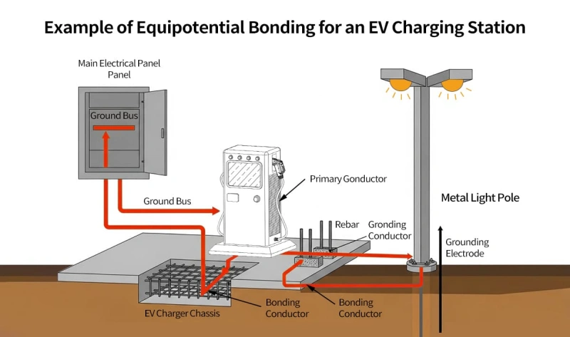
Feeder and Subpanel
- Applications: Commonly used to supply power from the main distribution panel to downstream distribution facilities, such as garage subpanels. Under the base conditions specified in NEC Table 310.16, the current-carrying capacity for 6 AWG copper wire in the 75°C column is 65 A, and for aluminum wire, it is 50 A.
- Common Selection Mistakes: Do not blindly apply the rule that “a 60A subpanel must use 6 AWG.” Wire gauge must be selected based on a comprehensive evaluation of the calculated load, terminal temperature rating, and whether derating is required.
Range (Electric Stove/Cooktop)
- Applicable Scenarios: Power supply circuits for high-power cooking appliances in residential settings.
- Selection Criteria: Do not blindly follow the common rule that “6 AWG is used for ranges.” Always refer to the appliance’s nameplate rating, voltage requirements, and specific manufacturer instructions.
HVAC
- Key Parameters: Select the wire based on the MCA (Minimum Circuit Amperage) listed on the equipment nameplate, and select the circuit breaker based on the MOCP (Maximum Overcurrent Protection).
- Special Rules: Due to inrush currents from compressors and motors, HVAC circuits must follow the specific NEC motor rules. It is normal for a circuit breaker’s rating to exceed the wire’s listed current-carrying capacity; this should not be automatically considered a design error.
Industrial Loads
- Applicable Scenarios: Motors, industrial heaters, control panel feeders, and small equipment branch circuits, etc.
- Complex Factors: In addition to consulting the listed current-carrying capacity, comprehensive consideration must be given to high temperatures in industrial environments, bundled wiring, mechanical vibration, oil contamination, chemical corrosion, and the continuous duty cycle of the equipment.
EV Chargers and Continuous Loads
EV Chargers and Continuous Load Sizing: Rules for Calculating Continuous Loads:
NEC and NFPA regulations (such as NEC 625.41) stipulate that EVSEs (Electric Vehicle Supply Equipment) are classified as continuous loads, and their feeder and branch circuit overcurrent protection must be calculated based on 125% of the maximum load.
Prerequisites for Matching a 6 AWG Conductor with a 60A Circuit:
The mere fact that a charger is rated at “48 A” does not directly imply that “6 AWG” must be used. A 6 AWG copper conductor has a current-carrying capacity of 65 A in the 75°C column of NEC Table 310.16; provided that the terminal and cable combination permits a 75°C rating, it can meet the requirements for a 60 A circuit; However, this may not apply if aluminum wire or specific restricted cables are used.
Termination Requirements for Prolonged High-Load Operation:
EV charging can continue for several hours, and even minute contact resistance at the connection points can lead to sustained heat generation.
Key Considerations:
Tighten bolts or wire terminals (lugs) strictly according to the manufacturer’s specified torque; verify that the terminal material is compatible with the conductor type; Check whether derating is required due to temperature or installation environment.
Adjustable Current and Energy Management:
If the EVSE supports adjustable current settings or includes an energy management system, the NEC permits calculating the load based on the system’s specified maximum actual output—provided code and equipment listing requirements are met—rather than designing solely based on the equipment’s theoretical limit.
Grounding and Bonding Applications
| Item | Purpose | Sizing Basis | Key Point |
|---|---|---|---|
| Grounding | Connects the system to earth or grounding electrodes | NEC Article 250 | Not sized from standard ampacity tables alone |
| Bonding | Keeps metal parts electrically connected and provides a fault-current path | NEC bonding requirements | Focus on low impedance and electrical continuity |
| GEC | Connects to the grounding electrode system | NEC 250.66 / Table 250.66 | Sized from service conductor size |
| EGC | Carries fault current so the OCPD can trip quickly | NEC Table 250.122 | Sized from upstream OCPD rating |
| Neutral | Carries normal return current | Based on load requirements | Different function from ground |
| Ground / EGC | Normally carries no load current; conducts during faults | Grounding rules | Do not confuse it with neutral |
Which 6 AWG Insulation and Cable Type Should You Choose?

Once you’ve determined that you need 6 AWG, you shouldn’t simply buy “6 AWG wire”; instead, you need to determine what type of insulation or cable it should be.
This is because the same 6 AWG conductor can be used to make THHN/THWN-2 or XHHW-2, or it can be incorporated into finished cables such as NM-B or UF-B. Although the conductor size may be the same, the environments in which they can be used vary greatly.
The correct selection process is as follows:
First, assess the installation environment; then, select the cable type; and finally, confirm that the wire gauge and current-carrying capacity meet the requirements.
THHN/THWN-2, XHHW-2, NM-B, UF-B, USE-2, and Welding Cable
| Type | Construction | Wet Location | Direct Burial | Typical Use | Key Note |
|---|---|---|---|---|---|
| THHN/THWN-2 | PVC insulation with nylon jacket | Yes, as THWN-2 | No | Conduit, feeders, branch circuits | Check for THWN-2 wet-location rating |
| XHHW-2 | XLPE-insulated building wire | Yes | Only if specifically listed | Feeders, service, industrial wiring | Wet-rated does not always mean direct burial |
| NM-B | Nonmetallic-sheathed cable | No | No | Indoor dry locations | Ampacity is generally limited to the 60°C column |
| UF-B | Moisture-resistant underground cable | Yes | Yes | Underground feeders, outdoor circuits | Thicker and stiffer than NM-B |
| USE-2 | Underground service-entrance conductor | Yes | Yes | Underground service entrance | USE-2 alone is not intended for general indoor wiring |
| Welding Cable | Fine-stranded, highly flexible cable | Depends on rating | Depends on listing | Welding leads, flexible equipment wiring | Do not use as building wire unless specifically approved |
Wet Locations, Direct Burial, Flexibility, and Temperature
1. Is it a wet location?
- Environmental Classification: A “wet location” refers not only to areas exposed to the elements, but also to underground conduits, outdoor cable trays, and the interiors of conduits prone to water accumulation or condensation.
- Selection Requirements: Cables explicitly rated for wet locations must be selected.
- Common Misconception: The belief that “cables inside PVC conduits will not come into contact with water” is incorrect. Even when run through conduits, the interior of underground or outdoor conduits can remain persistently damp due to condensation or seepage; the use of dry-location cables such as NM-B in such conduits is strictly prohibited.
2. Conduit or Direct Burial?
- Conceptual Difference: Direct-burial-rated cables (such as UF-B and USE-2) allow cables to be buried directly in soil without conduit protection; however, a “wet-rated” designation **is not the same as** a direct-burial rating.
- Pitfall Alert: Although THWN-2 and XHHW-2 offer excellent moisture resistance, they must not be buried without conduit. You must verify the cable markings, manufacturer’s datasheet, and listing certification; if “Direct Burial” is not explicitly stated, direct burial is strictly prohibited.
3. How much flexibility does the wiring require?
- Application Matching: Standard stranded wire is sufficient for fixed installations; high-strand-count flexible wire is required for frequent movement, repeated bending, or connecting equipment in confined spaces.
- Terminal Compatibility: Ultra-flexible conductors consist of a large number of fine strands, and their crimping characteristics differ from those of standard wire. When selecting high-flexibility wire, you must simultaneously verify that the terminals (Terminal/Lug) support the conductor’s flexibility class (Conductor Class).
4. Does a 90°C insulation rating mean the wire can be used at the 90°C current-carrying capacity?
- Conceptual Distinction: Insulation temperature rating ≠ actual allowable current-carrying capacity (Usable Ampacity).
- Limitation Rules: The actual current-carrying capacity of the entire circuit is limited by the temperature rating of the equipment terminals (Terminal Rating) and the provisions of the relevant standards.
How Far Can 6 AWG Wire Run Before Voltage Drop Matters?
There is no standard “maximum run length” for 6 AWG wire.
Voltage drop depends on the length of the circuit, current, system voltage, conductor material, and the actual resistance of the conductor; therefore, the maximum run length for the same 6 AWG wire can vary significantly depending on the load.
Voltage-Drop Inputs and Example Scenarios
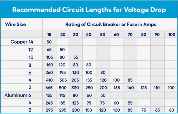
1. Key Parameters and Calculation Principles Affecting Voltage Drop
Core Parameters: System voltage, load current, one-way length, conductor material (copper/aluminum), conductor size, operating temperature, and AC/DC line characteristics.
Calculation Logic: For a single-phase two-wire circuit, current flows through both the outbound and return paths; therefore, the total path length is twice the one-way distance (e.g., a 100-ft one-way distance corresponds to a 200-ft conductor path).
2. The Effect of Distance and Voltage on Voltage Drop
The longer the distance, the greater the voltage drop: Under a 120V, 40A load (6 AWG copper wire):
50 ft (one-way): Voltage drop of approximately 1.98 V (1.65%)
150 ft (one-way): Voltage drop of approximately 5.94 V (4.95%)
Tip: Simply increasing the circuit length causes the voltage drop percentage to rise significantly; whether “6 AWG is sufficient” must be determined in conjunction with the distance.
When to Upsize the Conductor
Ampacity addresses the safety issue of “whether the wire will overheat”; voltage drop addresses the performance issue of “whether sufficient voltage can be delivered to the equipment.” Even if the wire’s ampacity meets requirements, the voltage drop may still exceed the limit during long-distance transmission.
- Significant Increase in Circuit Length: Voltage drop is directly proportional to distance. When a circuit reaches 100 ft, 150 ft, 200 ft, or longer, the voltage drop must be actively calculated; relying solely on the current-carrying capacity table is insufficient.
- Load Current Approaching Circuit Limits: Voltage drop is directly proportional to current. In circuits that are long and operate at high currents for extended periods, voltage drop is more significant, and an upgrade to 4 AWG or 3 AWG may be necessary.
- 120V high-current circuits: 120V systems are extremely sensitive to voltage drops (for example, a 4V loss represents 3.3% of 120V but only 1.7% of 240V); for long runs, upgrading to a larger gauge should be considered sooner.
- Inductive loads such as motors and compressors: A massive inrush current occurs when the equipment starts up, which can easily cause a voltage sag, leading to difficulty starting or tripping of the contactor; therefore, starting characteristics must be taken into account.
- The feeder has already consumed part of the voltage drop budget: the total voltage drop at the end-use equipment equals “feeder voltage drop + branch voltage drop.” The NEC recommends that branch voltage drop not exceed 3% and total voltage drop not exceed 5%; during design, calculations must be performed by cumulatively adding the voltage drops along the entire path from the power source.
6 AWG Copper vs. Aluminum: Which Is Better?
AWG simply indicates the size grade of a conductor. Because copper and aluminum have different material properties, their ampacity, resistance, weight, cost, and termination requirements will vary even if their cross-sectional dimensions are the same.
Copper is better suited for applications where you prioritize higher current-carrying capacity, lower voltage drop, smaller wire diameter, and simpler terminations.
Aluminum is better suited for applications where you prioritize weight and material cost, and where the equipment terminals explicitly support aluminum conductors.
There is no single “best” choice when selecting a wire; a more accurate approach is to compare the following factors together.
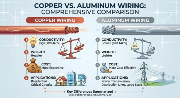
Ampacity, Resistance, Weight, Cost, and Termination
| Comparison | Copper | Aluminum | Selection Impact |
|---|---|---|---|
| Ampacity | Higher | Lower | Aluminum often needs a larger size |
| Resistance | Lower | Higher | Copper better controls voltage drop |
| Weight | Heavier | Lighter | Aluminum suits long, large-conductor runs |
| Cost | Higher | Lower | Aluminum can reduce feeder cost |
| Wire Size | Smaller for the same load | Larger for the same load | Aluminum may need more conduit and terminal space |
| Termination | Simpler | More demanding | Aluminum requires AL or CU/AL-rated terminals |
| Best For | Tight spaces, low voltage drop | Long runs, lower cost and weight | Choose by load, distance, and terminal limits |
How Do You Specify 6 AWG Wire for Procurement?
Specifying only the 6 AWG size informs the supplier of the conductor size, but does not indicate whether it is copper or aluminum, solid or stranded, what type of insulation is used, what color it is, how long it needs to be, or which certifications it must meet.
A more complete procurement specification should at least specify:
Conductor Material + AWG Size + Stranding + Insulation/Cable Type + Color + Length + Voltage/Temperature Rating + Required Certifications.
Conductor Material, Stranding, Insulation, Color, Length, and Certifications
| Item | Specify | Key Point |
|---|---|---|
| Conductor Material | Copper or Aluminum | Affects ampacity, resistance, and termination |
| Stranding | Solid, stranded, or conductor class | Affects flexibility and terminal fit |
| Insulation / Cable Type | THHN/THWN-2, XHHW-2, UF-B, etc. | Determines where the wire can be used |
| Color | Black, Red, White, Green, etc. | Match circuit identification requirements |
| Length | Total length and reel length | Avoid unwanted mid-run splices |
| Voltage Rating | e.g. 600 V | Must suit the system voltage |
| Temperature Rating | e.g. 75°C or 90°C | Affects installation and ampacity limits |
| Certification | UL or required project listing | Verify the exact part number |
| Wet / Dry Rating | Wet or dry location approval | Important for outdoor and underground conduit |
| Direct Burial | Direct-burial listed or not | Wet-rated does not mean burial-rated |
| Overall Diameter | Finished cable OD | Check conduit and connector fit |
| Reel / Packaging | e.g. 500 ft continuous reel | Confirm continuous run length |
Questions to Ask a Wire Supplier
| Question | Why It Matters |
|---|---|
| Copper or aluminum? | Affects ampacity and termination |
| What is the strand construction? | Confirms flexibility and terminal fit |
| What is the exact cable type? | Confirms insulation and application rating |
| Is it wet-location rated? | Required for wet or underground conduit |
| Is it direct-burial listed? | Wet-rated does not mean burial-rated |
| What are the voltage and temperature ratings? | Must match system requirements |
| What is the overall diameter? | Checks conduit and connector fit |
| What colors are available? | Supports correct circuit identification |
| What certifications does this part have? | Verify the exact product listing |
| What reel lengths are available? | Avoid unnecessary splices |
| Can you provide the datasheet? | Verify specifications in writing |
| Is the substitute fully equivalent? | Avoid non-equivalent 6 AWG replacements |
Frequently Asked Questions About 6 AWG Wire
q1: Can 6 AWG wire be used on a 60-amp breaker?
Yes, provided the following conditions are met: THHN/THWN-2 or similar 75°C+ insulation; equipment terminals rated for ≥75°C; and the run is short with no derating due to multiple wires in the same conduit. NM-B cable (60°C rating, 55A current-carrying capacity) is not suitable.
q2: Is 6 AWG wire suitable for a 48-amp EV charger?
Yes, it is suitable. A 48-amp continuous load requires a 60-amp circuit under the 125% rule, and the 65-amp current-carrying capacity of 75°C-rated 6 AWG copper wire meets this requirement. THHN/THWN-2 insulation must be used; NM-B cable is not suitable.
q3: What conduit size is needed for 6 AWG conductors?
A single conductor can use ½″ conduit; for three conductors (hot + neutral + ground), ¾″ conduit is recommended; for multiple conductors or long runs with many bends, the conduit size should generally be increased by one size. Verify based on the wire’s outer diameter and the NEC’s 40% fill ratio.
q4: Is 6 AWG the same as 16 mm²?
No, they are not the same. 6 AWG ≈ 13.3 mm², and 16 mm² is approximately 20% larger. These are only approximate equivalents; terminal selection must be based on the actual wire diameter and cannot be directly substituted.
Conclusion: 6 AWG wire: One Wire Size Fits Many Applications
As residential electrical distribution, electric vehicle charging, HVAC equipment, and industrial electrical systems place increasingly higher demands on current-carrying capacity, reliability, and installation flexibility, 6 AWG wire has become a very common conductor size for medium- to high-current applications.
When selecting a wire in practice, you cannot focus solely on the “6 AWG” wire size itself; you must comprehensively consider ampacity, conductor material, insulation type, terminal temperature rating, installation environment, circuit length, voltage drop, flexibility, and certification requirements.
If you are selecting 6 AWG wire for a specific project, Linkwings recommends prioritizing verification based on equipment requirements, applicable electrical codes, and the official datasheets provided by the wire manufacturer.

Nicole
The founder of Linkwings Electronics.
10+ Years Experience | 1000+ Global Projects Completed
Specialized in:
- Custom Wire Harness Assembly
- Automotive & Industrial Cable Harness Manufacturing
- Precision Crimping & Terminal Processing
- OEM / ODM Wire Harness Solutions
Need help with your project?
Let Linkwingselec deliver your next wire harness solution.