Aluminum Cable Ampacity Chart: Everything You Need To Know
Home » Aluminum Cable Ampacity Chart: Everything You Need To Know
Aluminum cables are lighter and less expensive than copper wires, offering advantages in applications involving large-gauge feeder lines and service entry cables. However, this is only true if you select the correct gauge. Choosing a gauge that’s too large wastes money, while choosing one that’s too small will result in failure to pass inspection. What’s even more dangerous is that if installation details—such as terminal oxidation or insufficient torque—are overlooked, the consequences may be even harder to detect than “insufficient wire gauge.”
This article serves as a practical guide to the current-carrying capacity of aluminum cables, covering everything from a column-by-column interpretation of the NEC 310.16 table to temperature adjustments, derating for multi-conductor cables, coordination of overcurrent protection, and the terminal handling and torque requirements specific to aluminum cables.
What Is the Ampacity of Aluminum Cable?
The current-carrying capacity of an aluminum cable refers to the maximum current (in amperes, A) that can continuously flow through an aluminum conductor under thermally stable conditions when the conductor reaches the maximum long-term operating temperature permitted by its insulation.
When it comes to aluminum cables, keep in mind that there is no fixed current-carrying capacity that applies regardless of specific conditions.
Key points:
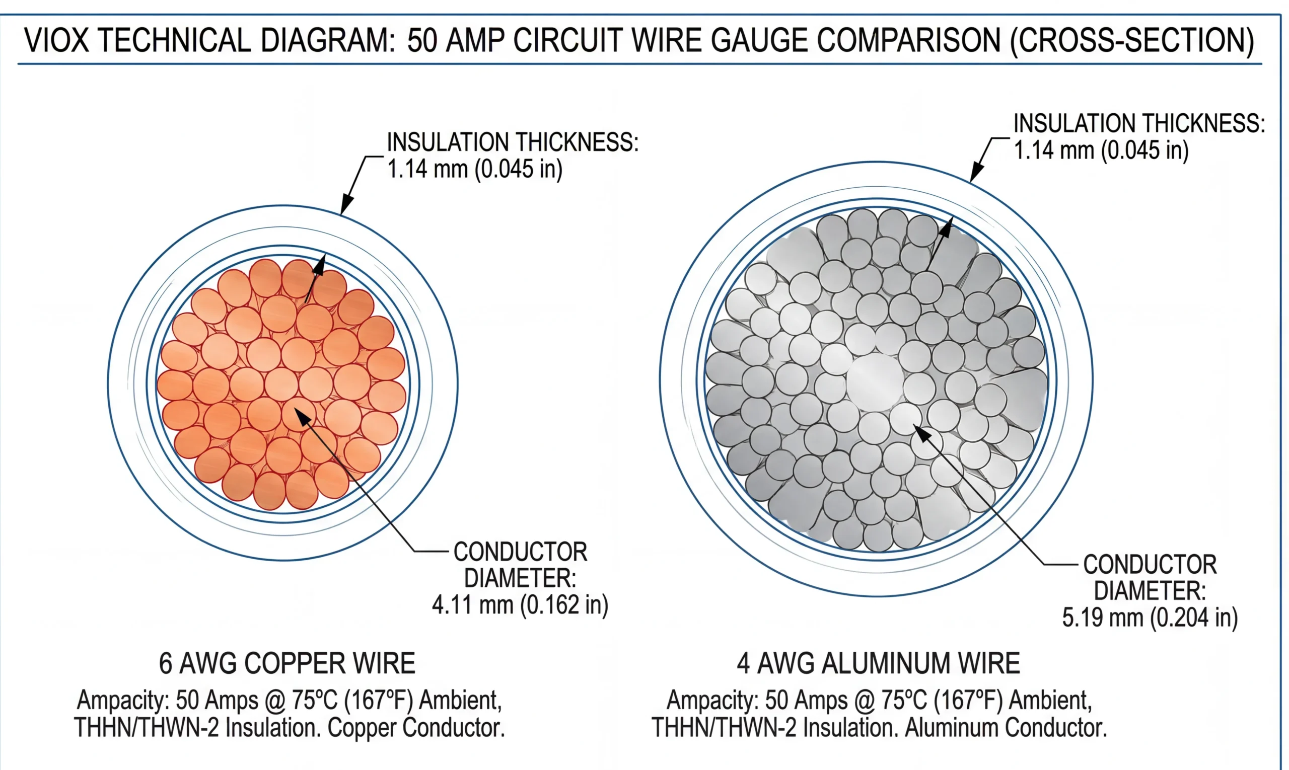
The current-carrying capacity of aluminum wire is approximately 60% to 78% of that of copper wire of the same gauge, because aluminum has a resistivity approximately 1.64 times that of copper.
- Common reference values for the safe current-carrying capacity of aluminum wires : 2.5 mm² ≈ 18 A, 4 mm² ≈ 25 A, 6 mm² ≈ 32 A, 10 mm² ≈ 42 A, 16 mm² ≈ 55 A, 25 mm² ≈ 70 A.
- The actual current-carrying capacity is influenced by various factors: the higher the ambient temperature, the lower the current-carrying capacity; a reduction factor applies when the cable is run through conduit or installed in parallel with multiple conductors; and the temperature rating of the insulation material also directly affects the value.
Therefore, the current-carrying capacity of aluminum cable is not a fixed value but is determined by a combination of factors, including wire diameter, insulation type, installation method, and ambient temperature.
Aluminum Cable Ampacity Chart by AWG and Temperature Rating
When reviewing an aluminum cable current-carrying capacity table, be sure to verify its applicable conditions. The data below is based on the section for aluminum or copper-clad aluminum conductors in NEC Table 310.16. The applicable conditions are: rated voltage of 0–2000 V, ambient temperature of 30°C (86°F), and no more than three current-carrying conductors in the same conduit or cable.
60°C, 75°C, and 90°C Ampacity Columns
| Aluminum Conductor Size | 60°C | 75°C | 90°C |
|---|---|---|---|
| 12 AWG | 15 A | 20 A | 25 A |
| 10 AWG | 25 A | 30 A | 35 A |
| 8 AWG | 35 A | 40 A | 45 A |
| 6 AWG | 40 A | 50 A | 55 A |
| 4 AWG | 55 A | 65 A | 75 A |
| 2 AWG | 75 A | 90 A | 100 A |
| 1/0 AWG | 100 A | 120 A | 135 A |
| 2/0 AWG | 115 A | 135 A | 150 A |
| 4/0 AWG | 150 A | 180 A | 205 A |
| 250 kcmil | 170 A | 205 A | 230 A |
| 500 kcmil | 260 A | 310 A | 350 A |
| 750 kcmil | 320 A | 385 A | 435 A |
| 1000 kcmil | 375 A | 445 A | 500 A |
| 1500 kcmil | 435 A | 520 A | 585 A |
| 2000 kcmil | 470 A | 560 A | 630 A |
AWG and kcmil Aluminum Conductor Sizes
AWG and kcmil are both methods for describing conductor size, but they are read differently.
AWG
It’s easy to get this mixed up: the smaller the number, the thicker the conductor. Therefore, the cross-sectional area increases in the following order: 12 AWG < 10 AWG < 8 AWG < 6 AWG < 4 AWG. After 1 AWG, the designations change to 1/0, 2/0, 3/0, and 4/0, with the conductors getting thicker in that order. Do not assume that 4/0 is smaller than 1/0. On the contrary, 4/0 is much thicker than 1/0.
Kcmil
For sizes larger than 4/0, continuing to use AWG designations becomes increasingly inconvenient, so the system switches to kcmil, which directly names the wire based on its cross-sectional area. This is much more intuitive than AWG: the larger the kcmil number, the thicker the conductor. The size sequence is 4/0 AWG → 250 kcmil → 300 kcmil → 500 kcmil → 1000 kcmil.
It is important to note that current-carrying capacity is not linearly proportional to cross-sectional area. This is because the heat generated inside larger conductors becomes increasingly difficult to dissipate through the surface.
The values in the table are only a starting point for preliminary selection. When making actual selections, any single condition—such as ambient temperature, the number of conductors in a bundle, the temperature rating of the insulation and terminals, or voltage drop—that is not met may require selecting a larger size.
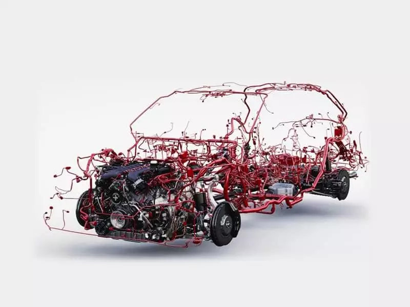
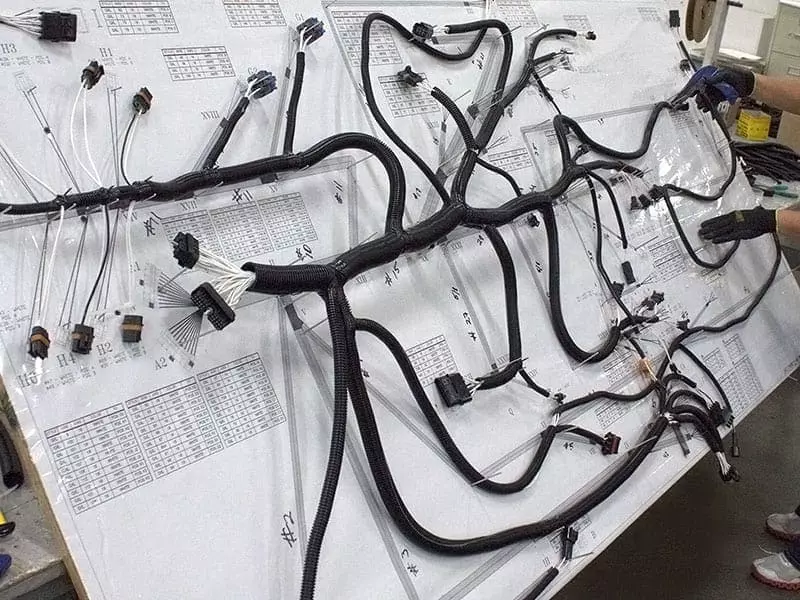
Tip: This table applies to NEC-compliant building and facility electrical installations; it cannot be directly applied to wiring harnesses in automobiles, construction machinery, or equipment—high temperatures, tightly packed wiring harnesses, terminal temperature rise, and OEM specifications in vehicles will all affect the final allowable current.
How Do You Read NEC Table 310.16 for Aluminum Conductors?
When consulting NEC Table 310.16, you cannot simply follow the steps of “find the wire size → look up the current.” The correct procedure is as follows:
First, confirm whether this table applies to your installation conditions → then confirm that the conductor material is aluminum → next, determine whether to use the 60°C, 75°C, or 90°C column → and finally, consider corrections such as ambient temperature and the number of current-carrying conductors.
NEC Table 310.16 is essentially a basic current-carrying capacity table. It tells you the basic allowable current-carrying capacity for insulated conductors of different AWG/kcmil sizes and temperature ratings under specified conditions.
Base Conditions Behind the Table Values
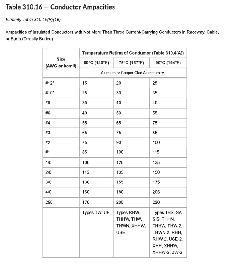
Before consulting the table, you must first review the underlying conditions. The current-carrying capacity values in NEC Table 310.16 apply to situations that meet all of the following conditions: conductor rated voltage of 0–2000 V, temperature class of 60°C / 75°C / 90°C, ambient temperature of 30°C, no more than three current-carrying conductors, and installation in conduits, cables, or direct burial, as specified.
The correct approach to reading this table is to understand that it does not provide a final answer, but rather a starting point for your calculations.
The correct selection logic is as follows:
1. Determine the current required by the equipment
2. Look up the table to find the base current-carrying capacity
3. Verify whether the actual installation conditions meet the base conditions
4. Determine whether an ambient temperature correction or adjustment for the number of current-carrying conductors is needed
5. Identify which column corresponds to the terminals’ allowable ratings
6. Confirm that the final result still meets the load requirements.
Tip: Based on our many years of industry experience, 30°C refers to the ambient temperature, not the conductor temperature. The 60°C / 75°C / 90°C listed at the top of the table refer to the temperature ratings of the conductor insulation, while the base ambient temperature used in the table is always 30°C.
Choosing the Correct Terminal Temperature Column
Principle: Do not rely solely on the temperature rating marked on the wire insulation; also consider the temperature rating of the equipment terminals. NEC 110.14(C) requires that the temperature rating used for conductor ampacity must not exceed the lowest allowable temperature rating among the terminals, conductors, and equipment.
Piping Analogy: If a pipe can withstand 100 bar but a valve can only withstand 70 bar, the entire system cannot be operated at 100 bar. The terminal is the limiting point of the circuit.
Default Rules: ≤100 A or 14 AWG–1 AWG: use 60°C; >100 A or greater than 1 AWG: use 75°C; if the equipment is explicitly marked or certified to allow a higher temperature, use the conditions specified on the marking. For actual projects, however, the specific equipment markings, listings, and the applicable version of the NEC should always take precedence.
Which Factors Require Aluminum Cable Derating?
1. Essence of Derating: When actual installation conditions are less favorable than the reference conditions in the ampacity table, the allowable current must be reduced; the original table values cannot be applied directly.
2. Two Key Reasons for Derating:
- Ambient temperature exceeds the reference temperature in the table
- More than three current-carrying conductors are present in the same conduit, cable tray, or cable.
3. Installation Methods Are Not Derating Factors: Raceway, cable, direct burial, and free air are not four separate “derating factors” in themselves, but rather determine which base ampacity table to use as a starting point.
4. Basic Calculation Framework: Allowable Ampacity = Base Table Value × Ambient Temperature Correction Factor × Number of Current-Carrying Conductors Adjustment Factor.
Tip: This formula is merely a conceptual framework; in actual engineering practice, the factors should not be multiplied mechanically. After calculating the correction values, you must also verify the terminal temperature rating limits and ultimately select the most stringent result among all conditions.
Ambient Temperature Correction
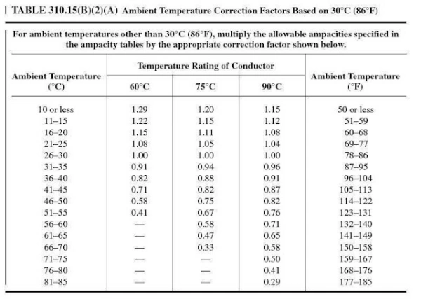
A key basic condition in NEC Table 310.16 is an ambient temperature of 30°C (86°F).
If your actual ambient temperature is not 30°C, you need to determine whether an ambient temperature correction applies.
Why does a higher temperature require derating?
Because conductors generate heat when an electric current flows through them. The hotter the environment, the lower the allowable continuous current.
The NEC’s 30°C reference ambient temperature correction table provides the corresponding correction factors.
| Ambient Temperature | 60°C | 75°C | 90°C |
|---|---|---|---|
| 26–30°C | 1.00 | 1.00 | 1.00 |
| 31–35°C | 0.91 | 0.94 | 0.96 |
| 36–40°C | 0.82 | 0.88 | 0.91 |
| 41–45°C | 0.71 | 0.82 | 0.87 |
| 46–50°C | 0.58 | 0.75 | 0.82 |
Please note that the 60°C / 75°C / 90°C listed here refer to conductor temperature ratings, not ambient temperature.
More Than Three Current-Carrying Conductors
The second important factor is the number of current-carrying conductors.
When multiple conductors that generate heat are crowded into the same conduit or cable, the heat accumulates, leading to poorer overall heat dissipation. The base current-carrying capacity in NEC Table 310.16 applies only to situations with no more than three current-carrying conductors.
If there are more than three, the actual number must be multiplied by the corresponding derating factor:
| Current-Carrying Conductors | Ampacity |
|---|---|
| 4–6 | 80% |
| 7–9 | 70% |
| 10–20 | 50% |
| 21–30 | 45% |
| 31–40 | 40% |
| 41+ | 35% |
Calculation Example
If the base current-carrying capacity of an aluminum conductor is 100 A, there are 6 current-carrying conductors under the same installation conditions, and the ambient temperature correction factor is 0.91, then the actual allowable current-carrying capacity is: 100 A × 0.91 × 80% = 72.8 A
Raceway, Cable, Direct-Burial, and Free-Air Conditions
| Installation Condition | How to Apply | Derating? | Key Check |
|---|---|---|---|
| Raceway | Use NEC Table 310.16 | No | Table values apply when base conditions are met, including 30°C ambient and ≤3 current-carrying conductors. |
| Cable | Use NEC Table 310.16 | No | Check conductor count and ambient temperature. |
| Direct Burial | Use Table 310.16 when applicable | No | Burial alone does not require a fixed derating factor. |
| Free Air | Use the applicable free-air table, such as Table 310.17 | No | Do not apply a made-up “free-air bonus” to Table 310.16. |
| High Ambient Temperature | Apply ambient-temperature correction | Yes | Table 310.16 is based on 30°C ambient. |
| More Than 3 Current-Carrying Conductors | Apply NEC 310.15(C)(1) adjustment factors | Yes | Count current-carrying conductors, not every conductor in the raceway or cable. |
| 90°C Conductor + 75°C Terminal | Use 90°C ampacity for permitted correction calculations, but respect the 75°C terminal limit | Depends | 90°C insulation does not make the final ampacity automatically equal to the 90°C column. |
| Automotive or Wrapped Wire Harness | Use vehicle standards, OEM rules, and cable/terminal data | N/A | Do not directly apply NEC building-wiring or free-air derating rules. |
How Do You Size Aluminum Cable for a Circuit?
When selecting aluminum cable for a circuit, you can’t simply calculate “load current ÷ some empirical factor” and then look up the AWG. A more reliable approach is:
First, calculate the design load → Determine if it’s a continuous load → Look up the base ampacity → Apply temperature and bundling factors → Coordinate with overcurrent protection devices → Then check for voltage drop, terminals, and installation conditions.
Note: Here, “ampacity” refers to the maximum current a conductor can continuously carry under specified installation and temperature conditions. An OCPD (overcurrent protective device) is a circuit breaker or fuse used to protect the conductor in the event of an overload or fault.
Tip: Here, “ampacity” refers to the maximum current a conductor can continuously carry under specified installation and temperature conditions. An OCPD (overcurrent protective device) is a circuit breaker or fuse used to protect the conductor in the event of an overload or fault.
Calculate the Load and Continuous-Load Requirement
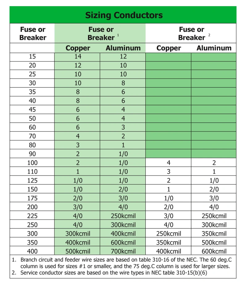
Step 1: Determine the Base Current
Before selecting a wire, calculate the actual current carried by the circuit. Use the rated current listed on the equipment nameplate as a priority. If only power and voltage are available, for simple DC or purely resistive single-phase loads, estimate the current using the formula I = P/V.
Core Rule: 125% Derating for Continuous Loads
The NEC defines a “Continuous Load” as a load for which the maximum current is expected to persist for 3 hours or more.
Calculation Example
Assume a circuit contains a 40A continuous load and a 15A intermittent load:
15A + (40A × 1.25) = 65A
In this case, the conductor must be selected based on a design current of 65A, not simply 55A. If the load consists entirely of 40A continuous loads, the design current is 50A. It is recommended to prioritize understanding the 125% calculation logic, as it aligns more closely with the NEC’s selection guidelines.
Apply Correction and Adjustment Factors
Core Principle: Base Current-Carrying Capacity ≠ Final Current-Carrying Capacity
Table 310.16 provides the base current-carrying capacity under ideal conditions (30°C ambient temperature, ≤3 current-carrying conductors). When actual operating conditions are more severe, correction factors (temperature) and adjustment factors (number of conductors) must be applied cumulatively.
Calculation Example
Assume that the base current-carrying capacity of an aluminum conductor is 100 A. Due to a high-temperature environment, it must be multiplied by a temperature correction factor of 0.91, and because there are 4–6 current-carrying conductors in the conduit, it must also be multiplied by an adjustment factor of 0.80: 100 A × 0.91 × 0.80 = 72.8 A
If the design current is 80 A, the conductor can actually carry only 72.8 A, which is unacceptable; a larger wire gauge must be selected.
Coordinate Ampacity with Overcurrent Protection
Core Principle: Protect the Conductor, Not the Equipment
The primary function of an OCPD (circuit breaker or fuse) is to protect the conductor and prevent it from reaching dangerous temperatures due to sustained overcurrent or a fault.
However, this is only a general guideline; actual selection must strictly adhere to the conductor protection requirements in NEC 240.4, standard OCPD ratings, and continuous load rules.
Selecting an OCPD for Continuous Loads
OCPD Rating ≥ Intermittent Load + 1.25 Times Continuous Load
For example, for a continuous load of 48 A, the calculated value is , so a 60 A OCPD must be selected.
Check Voltage Drop and Installation Constraints
1. Verifying Voltage Drop
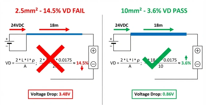
The current-carrying capacity only ensures that the cable does not overheat, while verifying the voltage drop determines whether the load end can obtain sufficient operating voltage. Since aluminum has a higher resistivity than copper, it experiences a greater voltage drop under the same conditions; this must be carefully calculated when supplying power over long distances.
- Design Criteria: The NEC recommends that branch circuit voltage drop not exceed 3%, and that the total voltage drop for the feeder and branch circuits not exceed 5%.
- Decision Logic: If the calculated voltage drop causes the voltage at the end of the circuit to fall below the minimum requirement of the equipment, the wire gauge must be increased even if the current-carrying capacity is met.
2. Verify Terminal Compatibility
The connection points of aluminum cables are the weakest links in the entire circuit; do not assume that copper terminals can be directly connected to aluminum wires.
- Label Verification: Confirm that the equipment terminals are clearly marked as compatible with aluminum conductors.
- Transition Connections: When connecting to a circuit breaker or making a T-branch connection, dedicated copper-to-aluminum transition terminals must be used; direct copper-to-aluminum bonding is prohibited to prevent poor contact caused by electrochemical corrosion.
3. Standardize Connection Procedures
The surface of aluminum conductors is highly prone to forming an insulating oxide layer and exhibits creep characteristics; the connection procedure directly determines the reliability of the joint.
- Surface Treatment: Before connection, use a specialized stainless steel wire brush to remove the oxide layer from the surface of the aluminum wire until the metallic luster is exposed, and apply an electrical-grade anti-oxidation compound grease.
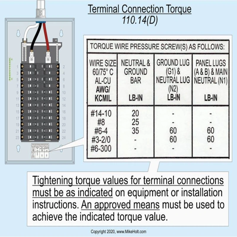
- Torque Tightening: Use a torque wrench to tighten the connection strictly according to the manufacturer’s specified torque values. After initial operation, re-inspect and retighten as specified to compensate for aluminum creep and relaxation.
4. Check Physical Space and Installation Conditions
After increasing the wire gauge, re-evaluate whether the on-site installation conditions meet the requirements.
- Bending Radius: The minimum bending radius for aluminum alloy cables is typically no less than 7 times the cable’s outer diameter; avoid deforming or damaging the armor during bending.
- Space Calculation: Confirm that, after increasing the wire gauge, the conduit fill rate and the bending space inside equipment remain compliant.
5. Evaluate Environmental and Mechanical Protection
- Environmental Compatibility: Confirm that environmental conditions—such as humidity, high temperatures, and corrosion—are suitable for the cable jacket.
- Mechanical Protection: Check whether the conductors will be subject to tension, abrasion, or mechanical damage during installation and operation; if necessary, install them in metal conduits or add protective devices.
Aluminum vs. Copper Ampacity: What Changes at the Same Load?
| Comparison | Copper | Aluminum | Sizing Impact |
|---|---|---|---|
| Conductivity | Higher | Lower | Copper has lower resistance at the same length and size. |
| Required Size | Smaller | Larger | Aluminum needs more conductor area for the same load. |
| Resistance & Voltage Drop | Lower | Higher | Aluminum may need upsizing to control heat and voltage drop. |
| Density | ≈ 8.9 g/cm³ | ≈ 30% of copper | Larger aluminum conductors can still weigh less. |
| Weight | Heavier | Lighter | Aluminum offers more weight savings on long, large conductors. |
| Installation Size | More compact | Larger | Copper is better where space or terminal size is limited. |
| Material Cost | Higher | Lower | Aluminum can reduce cost on long or large-conductor runs. |
| Core Trade-Off | Smaller size and better conductivity | Lower weight and cost with a larger size | Compare complete designs at the same load and voltage-drop target. |
Size, Resistance, Weight, Cost, and Termination Comparison
| Comparison | Copper | Aluminum | Sizing Impact |
|---|---|---|---|
| Ampacity | Higher | Lower | Aluminum needs a larger size for the same load. |
| Electrical Resistance | Lower | Higher | Aluminum may need upsizing to limit heat and voltage drop. |
| Physical Size | Smaller | Larger | Copper is better where space is limited. |
| Weight | Heavier | Lighter | Aluminum offers strong weight savings on long, large runs. |
| Conductor Cost | Higher | Lower | Aluminum is attractive for large or high-volume projects. |
| Termination | Compact and widely supported | Requires aluminum-rated terminals | Do not connect aluminum to copper-only terminals. |
| Voltage Drop | Lower | Higher | Long runs may require larger aluminum conductors. |
When Aluminum Is the Better Project Choice
Applications for aluminum share three common characteristics: high current, long distances, and ample space.
1. Large-cross-section, high-current applications
The larger the cross-section, the more exponentially the weight and material cost of copper increase, making aluminum’s economic advantages more pronounced. For example, the NFPA provides the following typical comparisons: 100 A corresponds to 4 AWG copper / 2 AWG aluminum; 110 A corresponds to 3 AWG copper / 1 AWG aluminum.
2. Long-Distance Wiring
Over long distances, the cumulative weight and cost of conductors become substantial, amplifying aluminum’s advantages of lightweight (with a density of only 30% that of copper) and low cost. However, voltage drops must be recalculated accordingly.
3. Ample Installation Space
Aluminum wires have a larger diameter, so sufficient clearance must be provided for equipment entry points, conduit fill rates, bending radii, and wiring space.
4. Equipment Terminals Explicitly Support Aluminum Connections
Implementation is easiest when power distribution equipment, circuit breakers, and terminal blocks all have established aluminum termination solutions.
5. Systems Highly Sensitive to Weighte
In weight-sensitive systems such as mobile equipment or vehicles, the weight-reduction benefits of aluminum are highly attractive. However, the NEC electrical load capacity tables for buildings cannot be directly applied to such systems; instead, the relevant industry standards must be followed.
What Installation Details Matter for Aluminum Conductors?
When installing aluminum conductors, it is important to ensure that the conductors, terminals, connection methods, and installation procedures are compatible with one another. Because aluminum and copper have different material properties, caution must be exercised at the termination points.
You can break down the installation inspection into four key points:
Are the terminals suitable for aluminum? → Is oxidation control required? → Are the terminals tightened to the specified torque? → Is the installation performed in accordance with applicable standards and the manufacturer’s instructions?
Listed Terminals, Oxide Control, Torque, and Workmanship
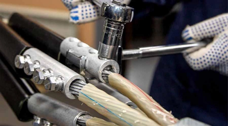
1. Terminal Selection:
NEC 110.14 explicitly stipulates that terminals must be suitable for the conductor material being connected. It is not sufficient to simply check whether “the hole is large enough to fit the conductor”; the markings on the equipment or terminals must be verified.
2. Oxidation Control:
An insulating oxide film easily forms on aluminum surfaces, but not all terminals require an additional anti-oxidant coating. Some specialized connectors are pre-filled with anti-oxidation material at the factory; removing or applying additional material without authorization will compromise the original design. Always follow the connector manufacturer’s installation instructions.
3. Tightening Torque:
Aluminum is a relatively soft material with creep characteristics. Insufficient torque will result in inadequate contact pressure and increased resistance. Excessive torque, on the other hand, may damage the conductor or deform the terminal.
4. Workmanship:
Proper termination requires precise wire stripping length, no damage to the strands, and no insulation pressed into the conductive area. Under no circumstances should strands be cut to force a thick aluminum wire into a small terminal, as this directly alters the effective cross-sectional area and creates serious safety hazards.
Code Edition, Local Rules, and Manufacturer Instructions
When installing aluminum conductors, there are three key things you should check.
1. First, confirm the specific edition of the code that applies to the project.
Don’t automatically apply the latest NEC. Different states, cities, or projects may use different editions of the NEC, and there may also be local amendments. In practice, the most reliable order is: project location → currently adopted NEC edition → local amendments → AHJ requirements.
2. Read the manufacturer’s instructions in conjunction with the code.
The NEC establishes general principles, but specific details—such as wire stripping length for terminals, allowed wire sizes, tightening torque, whether an oxidation inhibitor is required, and installation orientation—are often provided in product listings and manufacturer instructions. During actual installation, do not rely on habit to determine these parameters.
3. Ultimately, all requirements—including those of the code, the terminals, and the installation—must be met simultaneously.
The verification sequence is as follows: confirm that the terminal supports aluminum conductors → confirm the AWG/kcmil range → prepare the conductor and control oxidation as required → insert or crimp correctly → tighten to the specified torque → finally, confirm compliance with the equipment instructions and AHJ requirements.
Frequently Asked Questions About Aluminum Cable Ampacity
这是示例文本,单击 “编辑” 按钮更改此文本。
Q1: What size aluminum wire is used for a 100-amp service?
For standard short-distance installations, use 2 AWG aluminum wire; for longer distances (e.g., over 100 feet), voltage drop must be considered, and it is recommended to upgrade to 1/0 AWG.
Q2: Can a 90°C conductor use the 90°C ampacity as its final rating?
No. The final ampacity is limited by the terminal temperature rating (the “weakest link” principle).
For circuit breakers rated at 100 A or less, terminals are defaulted to a 60°C rating;
for terminals rated above 100 A or those explicitly marked, the rating is typically 75°C.
90°C insulation is used solely to calculate the derating factor; the final rating must be looked up in the corresponding 60°C or 75°C ampacity tables.
Q3: Is aluminum wire safe for feeders and service conductors?
It is safe and the industry standard.
Modern aluminum wire (such as SER cable) has been significantly optimized in terms of material and manufacturing processes. As long as it is used with terminals specifically designed for aluminum and tightened to the manufacturer’s specified torque, it is fully compliant and reliable for use as main service conductors and feeders.
Q4: Does voltage drop change the required aluminum wire size?
Yes.
For long-distance installations, voltage drop is a decisive factor. Aluminum wire has a relatively high resistivity, so voltage drop increases significantly over long distances, which can easily prevent equipment at the end of the line from starting up.
Selection principle: You must calculate both the “safe current-carrying capacity” and the “allowable voltage drop,” take the larger of the two values, and select the next higher standard size.
Conclusion: Aluminum Cable Ampacity Chart: Everything You Need To Know
The ampacity of aluminum cables cannot be determined solely by AWG, kcmil, or a single set of temperature data. A truly reliable selection requires a comprehensive consideration of the basic conditions in NEC Table 310.16, conductor temperature ratings, terminal temperature limits, ambient temperature, the number of current-carrying conductors, overcurrent protection, voltage drop, and the actual installation method.
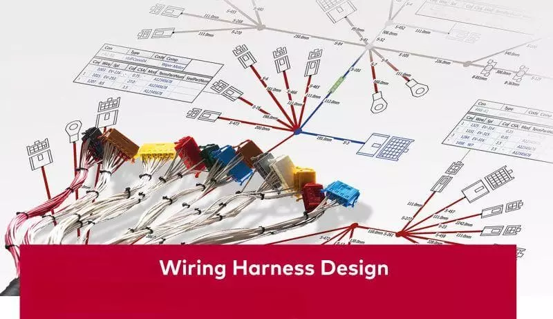
Collaborating with experienced wiring harness engineers or specialized suppliers early in the design process is crucial. By jointly confirming key parameters—such as current-carrying capacity, voltage drop, applicable code versions, and termination methods—we can eliminate potential hazards like overheating and oxidation-induced loosening at the source, ensuring the project is done right the first time.
Linkwings has over a decade of experience in automotive wiring harness design and has provided perfect automotive wiring harness design solutions to more than 200 clients worldwide! We welcome you to contact us!

Nicole
The founder of Linkwings Electronics.
10+ Years Experience | 1000+ Global Projects Completed
Specialized in:
- Custom Wire Harness Assembly
- Automotive & Industrial Cable Harness Manufacturing
- Precision Crimping & Terminal Processing
- OEM / ODM Wire Harness Solutions
Need help with your project?
Let Linkwingselec deliver your next wire harness solution.