Home » Trailer Wiring Harness Troubleshooting: Tests and Fixes
Have you encountered fault codes in your trailer wiring harness? A complete 7-pin wiring harness contains seven independent circuits, each responsible for a different electrical function—ground, lights, brake signals, and auxiliary power. When problems occur in some of these circuits, the symptoms may appear similar, but the causes can vary: oxidized ground connections, loose connector pins, internal wire breaks, load mismatches, or even a blown fuse on the tow vehicle’s end.
This article provides a circuit-by-circuit troubleshooting procedure to help you systematically and logically pinpoint the problem when dealing with trailer wiring harness malfunctions.
What should you check first when trailer lights do not work?
If the trailer lights aren’t working, you should first check whether the trailer socket on the tow vehicle is outputting the correct electrical signals; do not replace the bulbs or disassemble the trailer wiring harness directly.
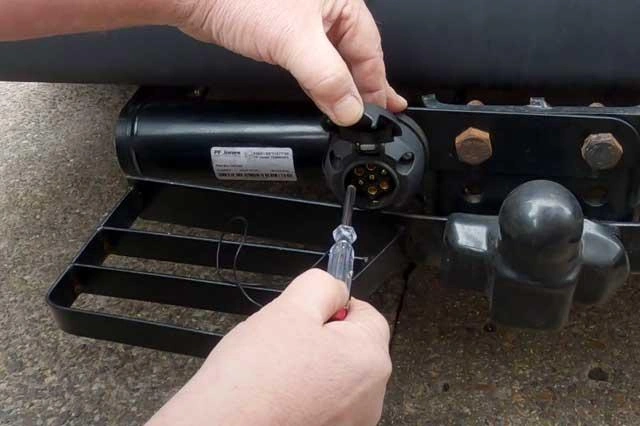
Step 1: Inspect the Trailer Socket on the Towing Vehicle
First, disconnect the trailer and inspect the towing vehicle’s socket for corrosion, water ingress, loose terminals, bent pins, or pin disengagement. Then, use a digital multimeter or a trailer light tester to check the taillights, left turn signal, right turn signal, and brake lights individually.
Different functions correspond to different circuits, so you must test each circuit individually based on the actual pin definitions.
Step 2: Isolate the Fault Based on Test Results
If the tow vehicle’s socket is not outputting the corresponding light signals, do not disassemble the trailer-side wiring harness just yet. Continue inspecting the vehicle-side fuses, wiring harness, connectors, and trailer control module.
If the tow vehicle’s socket is outputting the corresponding signals normally, this indicates that the vehicle side generally has normal power supply or control conditions. You should then shift the focus of your troubleshooting to the trailer plug, main cable, branch connectors, lights, and ground circuit.
Step 3: Don’t Overlook Grounding
If the output from the tractor is normal, but multiple lights on the trailer fail to illuminate simultaneously, dim, or light up in sequence, the ground circuit requires thorough inspection.
Grounding provides the path for the operating current of the lights to return to the negative terminal of the power source. Corrosion or looseness of the ground terminal, or issues with the contact surface caused by rust or coating, can all increase contact resistance.
Tip: Paint, primer coatings, rust, and even some sealants on the trailer frame can significantly increase contact resistance. When installing or repairing grounding terminals, be sure to sand the contact surfaces down to bare metal and apply dielectric grease after tightening to prevent future corrosion.
Tools for checking and testing a trailer wiring harness
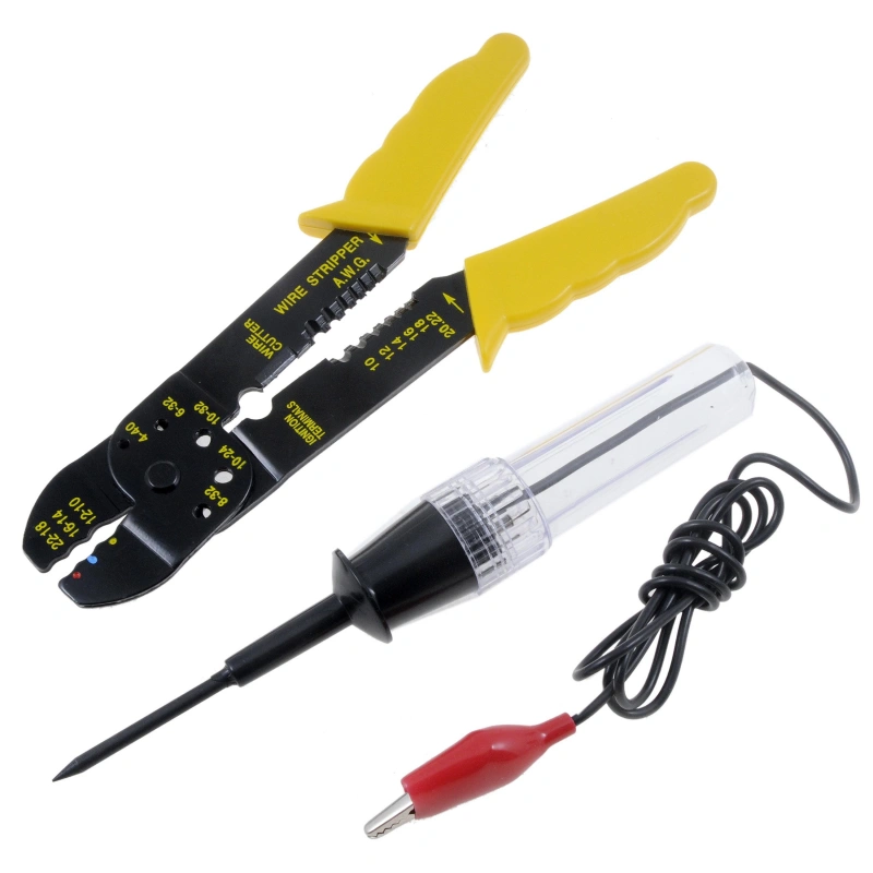
When inspecting and testing a trailer wiring harness, it is not recommended to use only a multimeter. A comprehensive diagnosis should cover several aspects, including voltage, continuity, ground, current, connector condition, and mechanical damage to the wires.
Inspection Tools:
| Tool | Primary Use | Key Inspection Points | Professional Notes |
|---|---|---|---|
| Flashlight / Inspection Light | Provides sufficient lighting for detailed visual inspection. | Damaged insulation, wear, cracks, crushing, heat damage, and water ingress. | Focus on frame pass-throughs, mounting points, and areas prone to friction. |
| Visual Inspection Tool / Magnifier | Identifies small defects in connectors and wiring. | Bent terminals, backed-out pins, oxidation, corrosion, and damaged seals. | Minor corrosion does not always mean circuit failure. Confirm with electrical testing. |
| Screwdrivers & Socket Tools | Checks and adjusts mounting hardware, grounds, and connectors. | Loose screws, bolts, ground terminals, and wiring clamps. | Disconnect power before removal. Avoid over-tightening during reassembly. |
| Terminal Removal Tool | Inspects or removes terminals inside connectors. | Loose terminals, backed-out pins, and damaged locking mechanisms. | Do not force terminals out with a screwdriver, as this can damage the terminal cavity or connector. |
| Cleaning Cloth / Lint-Free Cloth | Removes dust and dirt from connectors and wiring. | Contamination, oil, moisture, and mud. | Clean before assessing terminal condition to avoid mistaking dirt for corrosion. |
| Electrical Contact Cleaner | Cleans electrical connector terminals. | Oxidation, contaminants, and oil residue. | Confirm compatibility with connector plastics and sealing materials. |
| Wiring Diagram / Pinout Diagram | Identifies circuit and terminal functions. | Power, ground, tail lights, turn signals, brakes, and other circuits. | Do not rely only on wire colors. Always follow the applicable vehicle or harness wiring diagram. |
Testing Tools:
| Tool | Primary Use | Key Tests | Professional Notes |
|---|---|---|---|
| Digital Multimeter (DMM) | Measures voltage, resistance, and continuity. | Connector output, circuit continuity, and ground circuits. | The basic electrical diagnostic tool. Select the correct test mode and range before measuring. |
| Trailer Light Tester | Quickly verifies trailer connector circuits. | Tail lights, turn signals, brake lights, and other functions. | Helps determine whether the fault is on the vehicle or trailer side, often faster than testing individual terminals. |
| Test Light | Quickly checks whether power is present in a circuit. | Power output and lighting control signals. | Provides a basic power/no-power check and cannot replace a multimeter for precise voltage measurements. |
| Test Probes / Back-Probe Probes | Accesses test points without disconnecting the circuit. | Connector terminal voltage and signal output. | Use the correct probe size to avoid expanding terminals or causing poor contact. |
| Alligator Clip Test Leads | Provides a stable temporary test connection. | Ground, voltage, and voltage-drop tests. | Useful for continuous measurements and reduces errors caused by unstable probe contact. |
| Fuse Tester | Checks circuit protection components. | Trailer lighting and auxiliary power fuses. | If a fuse repeatedly blows, investigate the cause of the short circuit or overload instead of repeatedly replacing the fuse. |
| Voltage-Drop Tester / Multimeter | Measures voltage loss under load. | Poor grounds, high terminal resistance, and wiring connections. | Especially useful when continuity is normal but the circuit fails under load. More diagnostic than resistance testing alone. |
Separate the tow vehicle from the trailer
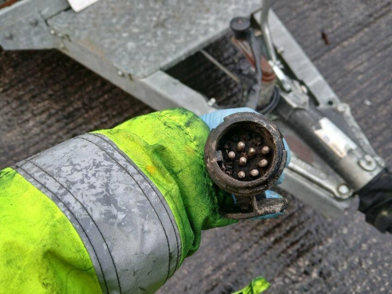
When troubleshooting trailer lighting issues, you should first disconnect the tow vehicle from the trailer so you can inspect them as two separate electrical systems.
1. Disconnect the connection and inspect the tow vehicle side
- First, disconnect the trailer connector, then inspect the tow vehicle side separately. Start by checking the tow vehicle’s connector for corrosion, bending, looseness, or water ingress.
- Using a digital multimeter or a trailer light tester, activate functions such as the taillights, left turn signal, right turn signal, and brake lights to check whether the terminals are providing the correct electrical signals.
- In modern vehicles, trailer lights may be controlled by the body control module (BCM) or a dedicated trailer module. Do not rely solely on traditional wire color codes or personal experience to determine terminal functions.
2. Troubleshoot Based on the Test Results of the Tow Vehicle’s Socket
If the tow vehicle’s socket itself is not providing the expected output, do not rush to inspect the trailer’s wiring harness. At this point, the fault is likely confined to the tow vehicle side. You should continue to inspect the relevant fuses, the vehicle’s wiring harness, connection points, and the trailer’s lighting control module, etc., according to the vehicle’s maintenance manual.
If the tow vehicle’s socket is outputting power normally but the corresponding lights still do not work after the trailer is connected, shift the focus of the troubleshooting to the trailer side.
- No output from the socket: Check the tow vehicle side first
- Output from the socket: Check the trailer side
3. Inspect the trailer side only after confirming normal output from the tow vehicle
After confirming that the tow vehicle’s socket is outputting the appropriate signals, inspect the trailer side separately. Focus on the trailer plug, main wiring harness, branch connection points, light fixtures, and ground connections.
You can start with a visual inspection and continuity tests. If the static continuity checks are normal but abnormalities persist when the lights are actually turned on, you should perform a voltage drop test.
4. Continue Troubleshooting by Specific Fault Circuits
This method of separate inspection is particularly suitable when the source of the fault is unclear, multiple lighting functions are malfunctioning simultaneously, or problems arise after the trailer’s wiring harness has been replaced.
This does not mean that the entire system must be completely disassembled every time; rather, it involves using connectors to quickly narrow down the scope of the fault.
How to test the vehicle-side trailer socket
To test the trailer socket on the towing vehicle, you must first verify that the towing vehicle can provide the correct lighting and power signals to the trailer.
1. Identify the Connector Type and Pin Assignment
Determine which type of trailer connector the vehicle uses and locate the corresponding wiring diagram.
The wiring diagram is used to identify the actual function of each pin or terminal, such as taillights, left turn signal, right turn signal, brake lights, ground, and auxiliary power.
2. Disconnect the Trailer and Perform a Visual Inspection
Before testing the vehicle-side socket, unplug the trailer plug so that the vehicle-side socket is not connected to a trailer.
Then inspect the socket for terminal corrosion or oxidation, bent or popped-out pins, foreign objects, dirt, or moisture.
3. Set Up the Digital Multimeter
To test with a digital multimeter, set the multimeter to DC voltage mode and select a range appropriate for the vehicle’s electrical system.
Connect the black probe to the ground terminal of the vehicle-side socket, and use the red probe to sequentially touch the functional terminals you wish to test.
Tip: Do not arbitrarily connect or short-circuit two terminals without understanding the pin definitions. Modern vehicles may use a body control module or a dedicated trailer module to control light output; incorrect operation may cause a fuse to blow or trigger electronic protection.
4. Test the Taillight/Contour Light Circuit
Turn on the vehicle’s taillights or contour lights, then touch the red probe to the corresponding taillight circuit terminal shown in the wiring diagram.
Check whether the multimeter reading shows a DC voltage output that matches the vehicle system’s status.
5. Test the Left and Right Turn Signal Circuits
Turn on the vehicle’s left and right turn signals separately, then test the corresponding terminals.
You need to verify the following:
When the left turn signal is on: A corresponding signal is present in the left turn signal circuit.
When the right turn signal is on: A corresponding signal is present in the right turn signal circuit.
6. Test the Brake Light Circuit
Press the vehicle’s brake pedal and measure the corresponding brake light circuit shown in the wiring diagram.
For systems with separate turn signal and brake circuits, test the corresponding terminals according to the specific wiring diagram; For systems with a shared turn signal and brake circuit, determine the appropriate procedure based on the actual circuit design.
7. Fault Isolation and Load Verification
If the voltages in each circuit are normal during no-load measurements, but the lights dim, flicker, or fail intermittently after connecting a trailer, further voltage drop tests under load are required to investigate whether the circuit has insufficient load-carrying capacity.
How to test the trailer plug and main cable
To test the trailer receptacle on the trailer, you must first verify that the tow vehicle can provide the correct lighting and power signals to the trailer.
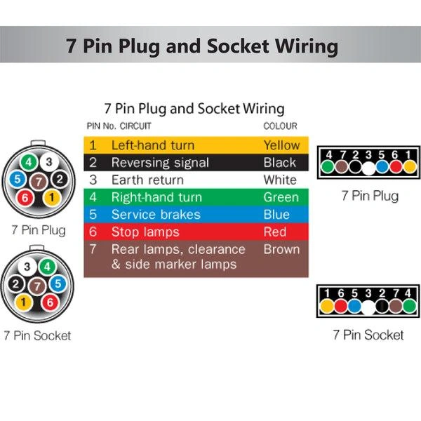
Step 1: Identify the Connector Type and Pin Assignment
Determine which type of trailer connector the vehicle uses—such as 4-Way Flat, 5-Way, 6-Way, or 7-Way—and locate the corresponding wiring diagram.
The wiring diagram is used to identify the actual function of each pin or terminal, such as taillights, left turn signal, right turn signal, brake lights, ground, and auxiliary power.
Step 2: Disconnect the Trailer and Perform a Visual Inspection
Before testing the vehicle-side socket, unplug the trailer plug so that the vehicle-side socket is not connected to a trailer.
Then inspect the socket for:
- Corrosion or oxidation on the terminals
- Bent or popped-out pins
- Foreign objects, dirt, or moisture
- Damage to the socket housing
- Loose or damaged wiring harness connections
Step 3: Check the Continuity of the Main Cable Circuit by Circuit
If the corresponding output on the vehicle side has been confirmed to be normal, you can then use the continuity or resistance test function on a digital multimeter to check whether there is a continuous connection between the trailer plug terminal and the other end of the main cable.
If you are troubleshooting the right turn signal, locate the right turn signal terminal on the trailer plug according to the wiring diagram, then trace the main wiring harness to find the corresponding wire or branch point, and check whether a continuous circuit is formed between the two ends.
Step 4: Check the Main Wiring Harness for Short Circuits
After confirming that the circuit is de-energized, use the wiring diagram to check for abnormal continuity between different circuits. If an unintended continuous connection is found between a lighting circuit and ground, further inspection is needed to determine whether there is damaged insulation, contact between the conductor and the vehicle frame, or an internal short circuit at a connector.
Step 5: Thoroughly Inspect the Grounding Points of the Main Cable
The grounding circuit of the trailer wiring harness is critical. Check whether the ground wire is securely connected to the specified grounding points, and inspect the grounding points for rust, paint, looseness, or mechanical damage.
Measuring static resistance with a multimeter can serve as a preliminary screening, but do not assume the grounding is normal simply because the resistance is low.
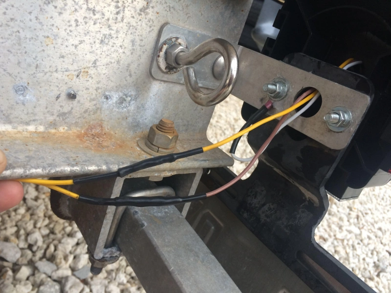
Step 6: Inspect the Main Cable for Mechanical Damage Along Its Route
If there are no obvious issues with the plug terminals or electrical continuity, you’ll need to inspect the main cable along its actual route.Pay close attention to:
Chassis penetration points → Wiring harness mounting points → Bends → Branch points → Connectors → Areas near the lights
Check for wear, pinching, stretching, excessive bending, or prolonged friction against the chassis.
Step 7: Perform a Dynamic Test for Intermittent Faults
If the trailer lights function normally when the vehicle is stationary but fail while driving, over bumps, or when turning, you can—provided safety is ensured—gently agitate the main cable and connection points to see if the electrical signal changes.
How to test trailer grounds
A ground fault in a trailer can easily cause multiple lights to fail simultaneously, dim, flicker, or interfere with each other’s operation.
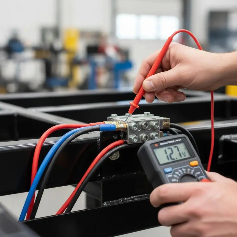
Check the Ground Connection
Disconnect the trailer from the tow vehicle, then locate where the trailer’s main ground wire connects to the chassis. Check the ground terminal for looseness, rust, oxidation, or paint buildup, and ensure the wire lugs and wires show no visible damage.
Test Ground Circuit Continuity
Using the resistance/continuity setting on a digital multimeter, check whether there is a continuous connection between the ground terminal on the trailer plug and the trailer’s ground point. If the display indicates an open circuit or the reading is noticeably unstable, focus your inspection on the ground wire, terminals, and connection points.
Perform a Voltage Drop Test
If the lights still exhibit abnormalities during actual operation, perform a voltage drop test. With the lights turned on, measure the voltage difference between the light’s ground terminal and the trailer plug’s ground terminal.
Tip: Based on our many years of industry experience, many trailers come from the factory with a corrosion-resistant coating on the bolts or brackets of the grounding points.
When installing or inspecting grounding points, be sure to use sandpaper or a wire brush to sand the contact surfaces until they reveal a bare metal sheen, and then apply an anti-oxidation grease to seal them off from the air and prevent future rust.
Troubleshoot by symptom
| Symptom | Check | Key Action |
|---|---|---|
| All Electrical Functions Fail | Connector | Confirm the 4-pin or 7-pin plug is fully locked. Check for corrosion, bent pins, or backed-out terminals. |
| Power Supply | Measure the 12V auxiliary pin to ground. If there is no voltage, check the vehicle fuse and relay. | |
| Ground Circuit | Measure resistance between the ground pin and vehicle frame. It should be ≤1Ω. | |
| Trailer Socket | Check for loose, corroded, or wet terminals inside the socket. | |
| One Light / One Side Not Working | Bulb | Check the filament visually or test continuity with a multimeter. |
| Light Socket | Check for deformed or oxidized contacts. | |
| Wiring | Test continuity from the corresponding connector pin to the faulty light to locate an open circuit. | |
| Ground Point | Measure contact resistance between the light mounting point and trailer frame. | |
| Dim Lights or Multiple Lights Glow | Likely Cause | Usually a poor ground, causing current to return through other lighting circuits. |
| Ground Resistance | Disconnect the connector and measure resistance from the trailer ground pin to the light housings. | |
| Ground Pin | Check Pin 1 for overheating, looseness, or insufficient contact. | |
| Additional Ground | If the original ground wire is undersized, add a ≥2.5 mm² ground wire to the main frame ground point. | |
| Fuse Blows After Connecting Trailer | Short Circuit | Disconnect the connector immediately. Do not repeatedly replace the fuse and reapply power. |
| Common Locations | Check pin-to-ground resistance. Inspect damaged wiring, wet light sockets, and debris bridging connector pins. | |
| Section Isolation | Disconnect lights or branch circuits one at a time to identify the faulty section. | |
| Electric Brake / Charging Circuit Not Working | Pin Voltage | Measure the brake and charging pins for voltage to ground. |
| Brake Controller | Confirm correct installation, settings, and output signal. | |
| Brake Coil | A typical brake magnet measures about 3–6Ω. An open or shorted coil requires replacement. | |
| Charging Voltage Drop | Measure voltage at the trailer battery under load. Excessive voltage drop can prevent proper charging. |
Frequently asked questions about trailer wiring tests
Q1: Can trailer wiring be tested without a trailer?
Yes. Ground one end of the circuit tester and connect the other end to the brake output pin. Press the brake pedal or manually move the controller slider. If the tester lights up normally, it indicates that the wiring on the tractor side and the brake controller output are functioning properly, and the fault lies on the trailer side.
Q2: Why does voltage appear with no load but fail with lights connected?
The reason is the presence of a high-impedance fault point in the circuit. A multimeter has extremely high internal resistance and draws almost no current during measurement, so the voltage is displayed normally even if there is a high-impedance point in the circuit. However, when a car headlight is connected, the load requires a significant amount of current, and the high-impedance point causes a significant voltage drop, resulting in insufficient voltage at the lamp terminal and causing the light to fail to illuminate or dim.
Q3: Can a test light damage vehicle electronics?
Incandescent test lamps draw a relatively high current and should not be used on low-current circuits, such as ECU signal lines or sensor circuits, as they may burn out internal resistors or precision components in the ECU.
Q4: What resistance should a trailer ground have?
The key resistance standards for the trailer grounding system are as follows:
- Between the end of the grounding strap and the vehicle frame: ≤4Ω
- Between any two points on metal components such as the chassis and tank: ≤5Ω
- From the grounding pin of the connector to the housing of each light fixture: ≤2Ω per section
Conclusion-Trailer Wiring Harness Troubleshooting: Tests and Fixes
Troubleshooting trailer wiring harnesses isn’t as simple as “changing a light bulb” or “checking a fuse”; it requires mastering the correct testing methods, understanding circuit logic, and strictly following the troubleshooting process. You can quickly pinpoint the root cause of the problem, reducing repeated disassembly and unnecessary rework caused by misdiagnosis.
As a brand specializing in wiring harness solutions, Linkwings is committed to providing users with high-quality trailer wiring harnesses, connector terminals, and professional testing tools. If you’re looking for reliable support for trailer electrical system maintenance, custom wiring harnesses, or fault repair, we invite you to explore Linkwings’ professional solutions to ensure that every connection stands the test of the road and time.

Nicole
The founder of Linkwings Electronics.
10+ Years Experience | 1000+ Global Projects Completed
Specialized in:
- Custom Wire Harness Assembly
- Automotive & Industrial Cable Harness Manufacturing
- Precision Crimping & Terminal Processing
- OEM / ODM Wire Harness Solutions
Need help with your project?
Let Linkwingselec deliver your next wire harness solution.