Cable Assembly 101: What It Is, Types, Process
Home » Cable Assembly 101: What It Is, Types, Process
Cable assemblies play a critical role in power transmission, signal transmission, data communication, and reliable connections between devices. From industrial equipment to medical devices, different applications place vastly different demands on their electrical performance, mechanical strength, environmental resistance, and manufacturing quality.
This article begins with the basic definition of cable assemblies and systematically introduces common types, design requirements, manufacturing processes, testing standards, and methods for procurement and supplier selection, helping you better understand how to properly design, validate, and procure a reliable cable assembly.
What Is a Cable Assembly?
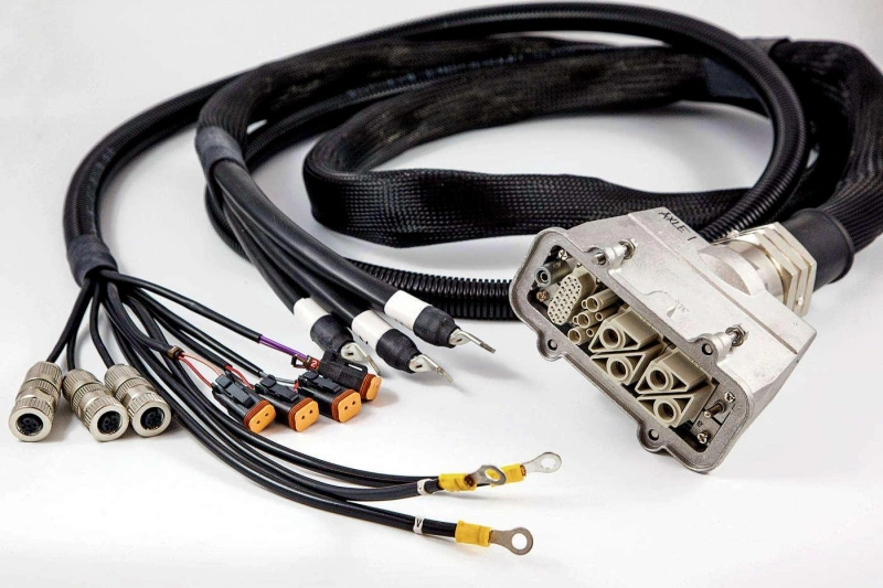
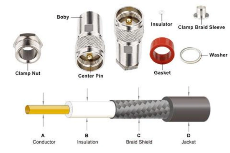
A cable assembly is essentially a finished functional component consisting of “cable + termination process,” rather than simply raw materials.
It consists of cables, connectors, terminals, and accessories such as protective sleeves. At least one end has undergone a termination process—such as crimping, soldering, or connector assembly—and is capable of directly establishing power, signal, or data communication connections between devices.
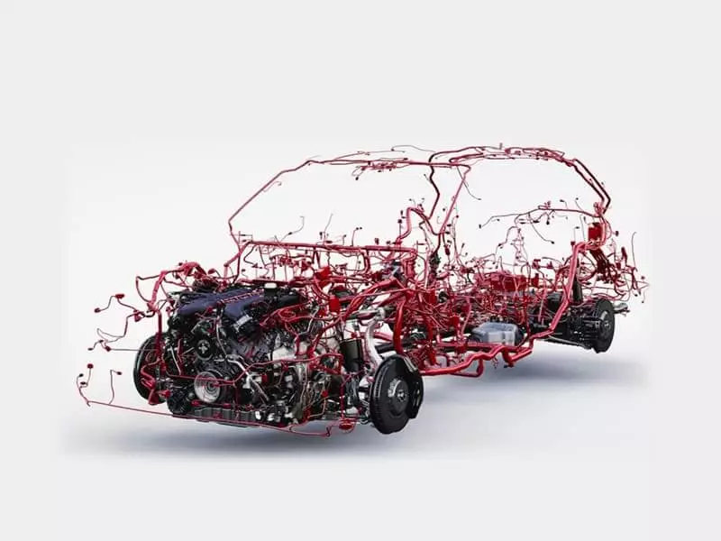
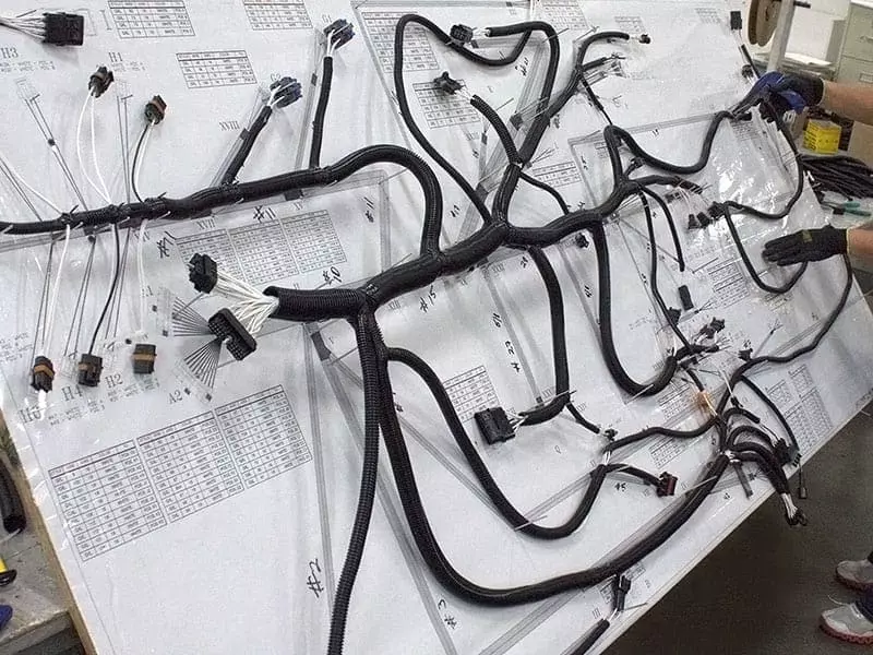
Cable Assembly vs. Wire Harness vs. Cable
| Comparison | Cable | Cable Assembly | Wire Harness |
|---|---|---|---|
| Definition | Basic cable for power, signal, or data transmission. | Finished cable with connectors for direct use. | Multiple wires organized into a complete system. |
| Structure | Conductor + insulation + shield/jacket. | Cable + connectors. | Wires + connectors + branches + protection. |
| Connectors | Optional. | Usually included. | Usually included. |
| Ready to Install | No, often needs processing. | Yes. | Yes. |
| Main Focus | Electrical performance and protection. | Connection reliability and interface matching. | Circuit routing and system integration. |
| Examples | Coaxial cable, data cable. | RF cable assembly, power cable assembly. | Automotive harness, equipment harness. |
| Choose When | You need raw cable. | You need a finished connection solution. | You need multiple circuits in one organized system. |
| Quick Check | Only the transmission medium? | Connectors and pinout already completed? | Multiple wires, branches, and routing required? |
Core Components and Their Functions
Core Components
Electrical Transmission and Insulation: Includes conductors that carry current and signals, insulation that prevents short circuits, and shielding that protects against electromagnetic interference.
Connection and Termination Structures: Connectors that interconnect devices and terminals that provide mechanical and electrical fastening.
Mechanical Protection and Accessories: The outer jacket that protects the entire cable; stress-relief structures that reduce direct tensile forces on terminals; and accessories such as labels, retaining clips, and wire protectors that facilitate mass production assembly.
Core Functions
Electrical Interconnection and Signal Integrity: Not only does this enable power transmission, data communication, and signal exchange between devices, but it also effectively suppresses electromagnetic interference in high-speed and RF scenarios through appropriate shielding and impedance design.
Mechanical Protection and Environmental Resistance: Structures such as the outer jacket and stress relief mechanisms resist friction, bending, vibration, and pulling, ensuring long-term reliability of components in harsh environments such as high temperatures, oily conditions, and water exposure.
Plug-and-Play and Error-Proof Assembly: Standardized termination and testing are completed before shipment. Clear pinout definitions and error-proofing accessories eliminate manual wiring errors on-site, significantly reducing equipment assembly and maintenance costs.
Tip: Thicker is not necessarily better. While larger conductors may reduce resistance and voltage drop, they also increase outer diameter and stiffness, and may even exceed the terminal’s applicable wire gauge range. Therefore, wire gauge should be determined based on a combination of current, length, voltage drop, and terminal capacity.
What Are the Main Types of Cable Assemblies?
There isn’t just one fixed structure for cable assemblies. You can classify them based on “what they transmit” or on “how they are manufactured and protected.”
The first level is based on function: whether they primarily transmit electricity, standard signals, high-speed data, radio frequency signals, or optical signals.
The second level is based on structure and operating environment: whether they are standard off-the-shelf products, custom designs, rubber-coated, shielded against interference, or ruggedized designs intended for harsh environments.
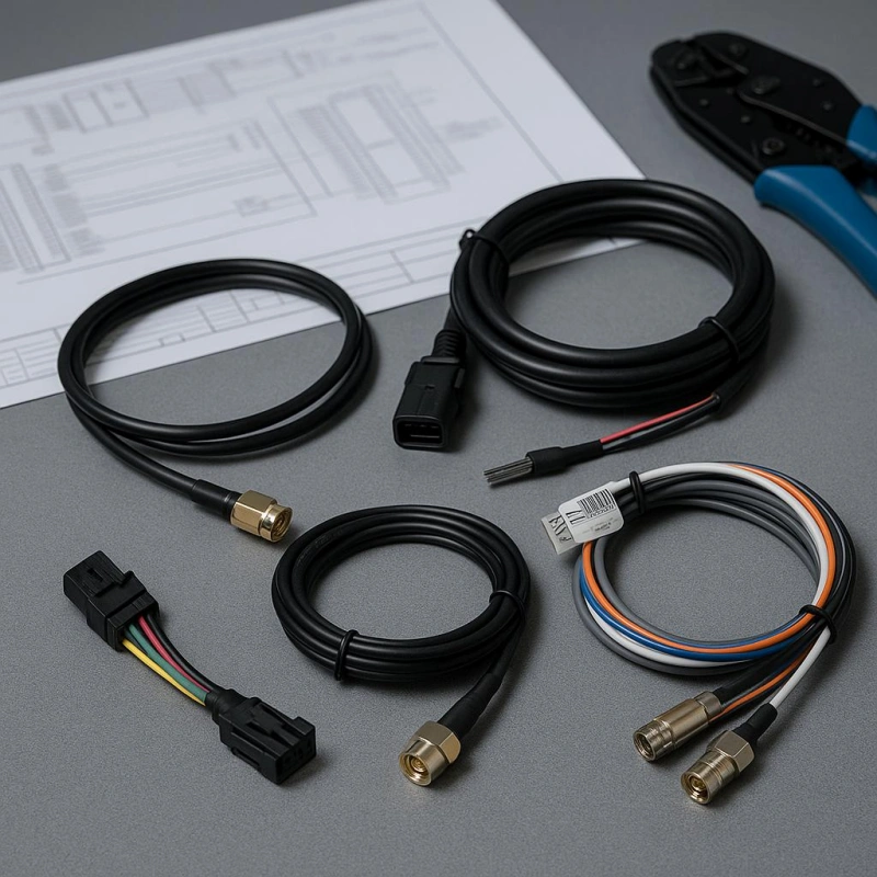
Power, Signal, Data, RF, Fiber, Flat, and Hybrid Assemblies
Power Cable Assembly:
Its primary function is to safely transmit electrical power. When selecting a cable, one cannot simply consider whether “the wire is thick enough”; instead, a comprehensive evaluation of the conductor cross-sectional area, current-carrying capacity, voltage drop, temperature rise, and the rated capacity of connectors and terminals is required to ensure that the entire power supply path remains within acceptable limits.
Signal Cable Assembly:
Primarily used to transmit control, sensor, and low-speed analog/digital signals. They are sensitive to noise and crosstalk; in applications involving weak signals, long cable runs, or proximity to strong interference sources, signal quality must be safeguarded through twisted-pair configuration, shielding, or proper routing.
Data Cable Assembly:
Responsible for high-speed digital data communication. Signal integrity is paramount, requiring extremely high standards for impedance matching, pair structure, shielding, and manufacturing consistency. The fact that physical interfaces are physically compatible does not guarantee electrical compatibility; arbitrary interchange is strictly prohibited.
RF Cable Assembly:
Used to transmit high-frequency RF signals, typically employing a coaxial cable structure. Selection requires strict verification of characteristic impedance, operating frequency, insertion loss, and connector matching; impedance mismatch can lead to severe signal reflection and loss.
Fiber Optic Cable Assembly:
Utilizes optical signals for transmission and is inherently immune to electromagnetic interference (EMI), making it the preferred choice for long distances, high bandwidth, and environments with strong electromagnetic fields. However, it is extremely sensitive to bend radius, end-face cleanliness, and connector quality; using it in short-distance, low-speed scenarios may actually increase costs.
Flat Cable Assembly:
Includes ribbon cables and flexible flat cables. Its greatest advantages are space savings and orderly cabling, making it ideal for connecting modules inside narrow equipment; however, in harsh mechanical environments requiring frequent three-dimensional bending or subject to significant tensile stress, it is less reliable than traditional round cables.
Hybrid Cable Assembly:
Integrates power, data, and even fiber optics within a single assembly. It effectively reduces the number of cables and simplifies routing; however, the design is complex and requires a well-planned internal layout, shielding, and grounding to address issues such as power noise interference with weak signals or high-speed data, as well as heat dissipation.
Standard, Custom, Overmolded, Shielded, and Ruggedized Designs
Standard Cable Assembly:
Refers to off-the-shelf products with fixed specifications, lengths, connectors, and pinouts. The advantages include convenient procurement, controllable costs, and straightforward lead times; however, this requires a perfect match with the equipment’s interfaces and spatial constraints. Under no circumstances should incompatible standard cables be forced into use simply for the sake of convenience.
Custom Cable Assembly:
Designed and manufactured specifically to meet project requirements, allowing for the customization of connectors, pinouts, wiring, and mechanical protection structures. Suitable for projects with unique structural requirements or those requiring long-term, stable mass production; however, design should be restrained—customize only what is truly necessary to avoid unnecessarily increasing supply chain complexity and maintenance difficulties.
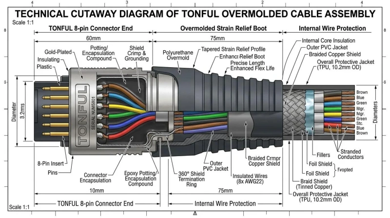
Overmolded Cable Assembly:
Plastic or elastic material is overmolded at the connection point between the connector and the cable. Its core value lies in providing stress relief, mechanical protection, and a uniform appearance, making it suitable for frequent plugging and unplugging or outdoor applications; however, overmolding does not guarantee absolute waterproofing, and for fixed connections inside equipment, it only adds unnecessary costs.
Shielded Cable Assembly:
Reduces electromagnetic interference (EMI) through metal foil or braided shielding, making it essential for high-speed data, RF, and weak analog signal applications. However, the shielding layer increases the outer diameter and cost while reducing flexibility. Furthermore, shielding effectiveness depends entirely on the termination process at the connector; one must not merely consider “whether shielding is present,” but must verify “how the shielding layer is terminated.”
Ruggedized Cable Assembly:
Designed for harsh environments such as vibration, shock, extreme temperatures, and exposure to chemicals, these assemblies feature more abrasion-resistant jackets, reliable locking connectors, and sealed structures. However, “ruggedization” is not a uniform rating; when selecting a product, you must confirm with the supplier the specific environmental conditions it can withstand and the corresponding test standards.
Which Requirements Define a Cable Assembly?
What truly determines whether a cable assembly can operate reliably over the long term is a comprehensive set of electrical, mechanical, and environmental requirements.
You can think of these requirements in terms of three levels:
1. First, verify that it can properly transmit power and signals;
2. Second, verify that it can withstand bending, tension, and vibration during actual installation;
3. Finally, verify that it can withstand environmental factors such as temperature, chemicals, moisture, UV radiation, and dust.
Electrical Load, Signal Integrity, and Pinout
Electrical Load
When selecting a connector, it is necessary to comprehensively consider the operating current, peak current, harness length, and voltage drop. Ensure that the rated current-carrying capacity of the connector and terminals matches that of the wires; otherwise, a single weak link will limit the performance of the entire assembly.
Signal Integrity
A continuity test with a multimeter only confirms the absence of an open circuit; it cannot verify the waveform and timing quality of high-speed data, RF, or sensitive signals. In such scenarios, impedance matching, shielding structures, and wire-pair design must be strictly controlled; ordinary copper wire must never be used as a substitute.
Pin Definition
This is the key factor determining whether components are interchangeable. Even if the connector model and length are identical, a different internal pinout can result in anything from the component failing to function to, in severe cases, burning out the equipment. When customizing or purchasing, a complete pin-to-pin mapping must be provided.
Flexing, Pull Force, Bend Radius, Vibration, and Strain Relief
| Mechanical Requirement | Definition | When Important | Common Risks | Design Considerations |
|---|---|---|---|---|
| Flexing | Cable assembly bending or moving repeatedly during use. | Robots, drag chains, moving equipment, frequent opening/closing. | Conductor fatigue, shield damage, internal breaks. | Identify fixed or dynamic use. Flexible does not always mean flex-life rated. |
| Pull Force | Mechanical force applied to the cable or connection area. | Frequent plugging, heavy cables, hanging installations. | Loose terminals, damaged solder joints, broken conductors. | Prevent pulling force from acting directly on terminals and conductors. |
| Strain Relief | Distributes bending and pulling stress over a larger area. | Frequent bending, plugging, or cable movement. | Stress concentration near connector exits and early failure. | Use boots, clamps, heat shrink, or overmolding. |
| Bend Radius | Minimum allowed cable bending radius. | Limited space, thick cables, fiber, or shielded cables. | Damage to conductor, insulation, shield, or fiber. | Reserve proper bending space and avoid sharp bends near connectors. |
| Vibration | Long-term mechanical vibration during operation. | Automotive, industrial equipment, motors, moving machines. | Connector loosening, terminal wear, conductor fatigue. | Check locking features, mounting points, strain relief, and cable slack. |
Temperature, Chemicals, Moisture, UV, and Ingress Protection
Temperature:
The extreme high and low temperatures at the cable’s actual installation location must be clearly identified. High temperatures can cause insulation and seals to age, while low temperatures can make materials brittle. When selecting a cable, check the temperature ratings of all components, including connectors, terminals, and overmolding.
Chemical Resistance:
If the cable will come into contact with oils, fuels, coolants, etc., the compatibility of the jacket and sealing materials must be confirmed. It is strictly prohibited to use the generic term “industrial grade” in place of specific requirements; the specific media with which the cable will come into contact must be clearly identified, and material data sheets must be carefully verified.
Moisture & IP:
Condensation, rain splash, and prolonged immersion impose vastly different sealing requirements. Do not equate the connector’s IP rating with that of the entire cable; the actual sealing performance of the entire cable also depends on proper pairing, wire gauge matching, end caps, and termination techniques.
UV Resistance:
This is not a major concern for internal equipment cabling; however, for cables exposed to the outdoors for extended periods, it is essential to explicitly specify sheaths and exposed materials with UV resistance to prevent material aging, cracking, and loss of mechanical strength caused by direct sunlight.
How Is a Cable Assembly Designed for Manufacturability?
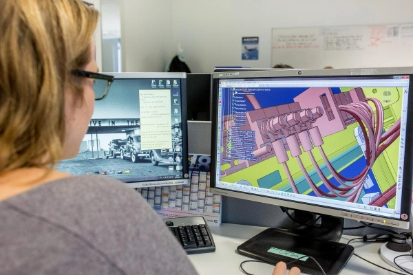
When designing a cable assembly, it is not enough to simply consider whether it “works electrically”; one must also consider whether it can be manufactured consistently and repeatably. This is known as Design for Manufacturability, or DFM for short.
You can think of DFM as taking into account manufacturing, assembly, inspection, and mass production early in the design phase, rather than waiting until the drawings are complete and then leaving it up to the factory to figure out how to “make it happen.”
Drawings, BOM, Tolerances, Critical Characteristics, and Revision Control
Drawing:
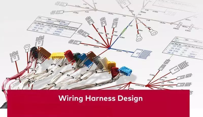
A drawing is a document that specifies manufacturing and inspection standards; it is not merely a rough sketch of the appearance. It must clearly indicate key assembly requirements such as connector location, pinout, branch dimensions, label placement, and wire exit direction.
BOM:
Used to specify the complete list of materials and components. Mass-production projects must use specific part numbers; vague descriptions such as “black wire” or “a certain brand of connector” are not permitted.
Tolerance:
Indicates the permissible range of deviation from specified dimensions. Tighter tolerances are not necessarily better; excessively tight tolerances can significantly increase the complexity of jigs and tooling as well as manufacturing costs.
Critical Characteristics:
These are features that, if exceeded, will directly affect assembly, functionality, safety, or reliability. Do not designate all dimensions as critical characteristics; they must be precisely identified based on the product’s functionality.
Revision Control:
Strict version control must be maintained for documents such as drawings, BOMs, and pinouts. For every design change, it must be clearly stated “what was changed, why it was changed, when the change takes effect, and how to handle existing inventory.”
Connector, Wire, Shielding, Jacket, and Overmold Compatibility
| Compatibility | What to Check | Why It Matters | Common Issues |
|---|---|---|---|
| Wire ↔ Terminal | Conductor size, insulation diameter, terminal wire range. | Ensures proper crimping and electrical/mechanical connection. | Wire too small: weak crimp. Wire too large: cannot crimp or fit. |
| Terminal ↔ Connector | Terminal series, size, locking structure, insertion direction. | Ensures correct insertion and locking in connector housing. | Incomplete insertion, lock failure, wrong orientation. |
| Cable ↔ Connector | Cable diameter, backshell size, exit space, strain relief range. | Ensures proper cable entry and secure fixing. | Cable too large to fit; too small for clamping or sealing. |
| Shield ↔ Connector | Shield structure, termination method, strip length, rear space. | Shield performance depends on termination, not only cable type. | Poor grounding, excessive strip length, insufficient space. |
| Jacket ↔ Seal | Jacket diameter, surface condition, seal range. | Creates reliable environmental sealing. | Seal failure due to incorrect jacket size. |
| Jacket ↔ Overmold | Material compatibility and bonding structure. | Ensures long-term attachment between cable and overmold. | Peeling, cracking, or interface separation. |
| Connector ↔ Overmold | Connector material, molding conditions, available space. | Prevents connector damage and installation issues. | Connector deformation, oversized molding, housing interference. |
| Shield ↔ Jacket / Overmold | Shield coverage and termination method. | Maintains EMI protection and mechanical coverage. | Exposed shield, poor continuity, damaged shielding. |
| Overall Dimension | Connector, cable, seal, boot, and overmold dimensions. | All parts must fit together as a complete assembly. | Assembly space issues, wrong exit angle, poor equipment fit. |
How Are Cable Assemblies Manufactured?
The manufacturing of cable assemblies involves processing components such as wire, cable, terminals, connectors, shielding, heat-shrink tubing, and labels in accordance with drawings and process requirements to create a finished product that can be reliably installed and used.
Cutting, Stripping, Crimping, Soldering, and Termination
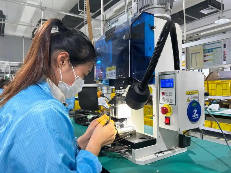
Step 1: Cutting
This is the starting point of the manufacturing process, where coiled wire is cut to the specified length according to the drawings. The key is to establish a clear measurement reference and allow for sufficient processing allowance for subsequent stripping and terminating, thereby preventing dimensional deviations in the final product caused by an ambiguous reference.
Step 2: Stripping
Remove the insulation to expose the metal conductor. The key is to precisely control the stripping length and strictly avoid damaging the core wire. Stripping too short can result in an unstable crimp, while stripping too long increases the risk of short circuits due to exposed copper. Furthermore, cuts to the conductor reduce the effective cross-sectional area, making it highly susceptible to fatigue failure in vibrating environments. For coaxial or multi-layer cables with a shielding layer, the stripping length must be controlled on a layer-by-layer basis.
Step 3: Crimping
This process secures the terminal to the conductor through mechanical deformation and is the most common termination method in automotive wiring harnesses. A qualified crimp must simultaneously meet conductor crimping and insulation support requirements, and the terminal must strictly match the wire gauge and conductor structure. It is strictly prohibited to arbitrarily substitute soldering for terminals designed for crimping.
Step 4: Soldering
This process establishes an electrical connection using solder and is commonly used for PCB connections or in specific rework scenarios. Soldering is not inherently superior to crimping; solder penetration can cause localized hardening of the wire, leading to stress concentration during repeated bending. Additionally, high temperatures can damage the insulation or internal materials of connectors. Therefore, soldering is not recommended in high-vibration environments.
Step 5: Termination
This is the collective term for the preceding steps, referring to the process of establishing a reliable electrical connection between the cable end and a terminal, connector, or PCB. When selecting a termination method, priority should be given to following the connector manufacturer’s design specifications and comprehensively evaluating the vibration and bending requirements of the application scenario, rather than relying on personal preference.
Connector Loading, Shield Termination, Overmolding, and Labeling
| Manufacturing Step | What It Is | Why Important | Key Checks | Common Errors |
|---|---|---|---|---|
| Connector Loading | Insert terminals into the correct connector positions. | Wrong pin location causes assembly failure. | Pinout, insertion depth, secondary lock. | Wrong pin, loose terminal, unlocked lock. |
| Shield Termination | Connect shield to the required ground or shell. | Ensures EMI protection and signal performance. | Shield length, grounding, fixing method. | Poor grounding, excessive shield stripping. |
| Overmolding | Mold protection material around cable and connector. | Improves strain relief and protection. | Material, size, cable exit direction. | Oversize, interference, poor bonding. |
| Labeling | Add part numbers and traceability marks. | Supports identification and tracking. | Content, location, durability. | Wrong label, peeling, unreadable marks. |
In-Process Inspection and Final Assembly
In-Process Inspection: The key principle is “early detection and early correction”; inspections should not be left until the very end. Immediately after completing critical processes such as crimping, housing insertion, and shield termination, it is necessary to check for terminal deformation, pinout accuracy, and locking status.
Final Assembly: This includes installing accessories such as heat-shrink tubing, waterproof plugs, clips, and cable ties, as well as organizing the routing of the wiring harness. At the same time, it is necessary to verify that the overall dimensions, connector orientation, and label positions conform to the drawings.
How Are Cable Assemblies Tested and Qualified?
After a cable assembly is manufactured, it must be verified—based on its intended use—to ensure that the wiring is correct, the insulation is reliable, the terminations are secure, and that its actual functionality meets the requirements.
Tip:Not all of the tests listed below need to be performed on every cable assembly. The test items, parameters, and sampling methods should be determined based on the product’s intended use, risk level, customer specifications, and applicable standards.
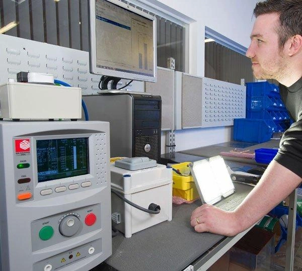
Continuity, Hipot, Insulation Resistance, Pull, and Functional Tests
| Test | Main Check | When Important | Common Misunderstanding |
|---|---|---|---|
| Continuity Test | Open circuit, short circuit, wrong wiring, pinout. | Almost all multi-wire cable assemblies. | Passing continuity does not mean the assembly is fully qualified. |
| Hipot Test | Insulation withstands specified voltage without breakdown. | High-voltage products or strict insulation requirements. | Higher test voltage is not always safer. |
| Insulation Resistance Test | Insulation resistance between isolated circuits. | Products requiring insulation performance verification. | IR test and Hipot test are not the same. |
| Pull Test | Mechanical strength of terminal and wire connection. | Crimp validation, first article, or sampling inspection. | Not every finished cable needs destructive testing. |
| Functional Test | Actual performance in the application. | Data, RF, electronic, or special-function assemblies. | Power-on or continuity alone is not full validation. |
IPC/WHMA-A-620, UL, RoHS, REACH, and Industry-Specific Requirements
| Requirement | Main Purpose | Does It Validate Product Performance? |
|---|---|---|
| IPC/WHMA-A-620 | Cable and wire harness manufacturing, assembly quality, and acceptance criteria. | No. It does not replace electrical, environmental, or life testing. |
| UL | Safety, material, and certification requirements for specific products and applications. | Depends on the specific UL standard, project, and certification scope. |
| RoHS | Restricts certain hazardous substances in electrical and electronic products. | No. It does not confirm electrical or mechanical performance. |
| REACH | Chemical substance management, SVHC information, and related restrictions. | No. It does not confirm electrical or mechanical performance. |
| Industry-Specific Requirements | Customer and industry requirements for safety, reliability, and validation. | Depends on standards, customer specifications, and required tests. |
Custom vs. Off-the-Shelf Cable Assemblies: Which Should You Choose?
There is no definitive answer to whether you should choose a custom cable assembly or an off-the-shelf cable assembly. What really matters is whether your product requirements exceed what standard products can reliably meet.
| Type | Core Advantages | Suitable When | Costs / Limitations |
|---|---|---|---|
| Off-the-Shelf (Standard) | Fast delivery, easy purchasing, no development effort, easy replacement. | Connector, pinout, length, current, and signal requirements are already satisfied. | Limited flexibility; fixed specifications may need to be accepted. |
| Custom | Fully matches equipment requirements with custom wire size, length, pinout, shielding, branches, and overmold. | Special structures, mass production, or specific performance requirements. | Requires engineering drawings, BOM, prototypes, validation, and version management. |
Cost, Lead Time, Performance, Volume, and Lifecycle Tradeoffs
Cost:
The total cost must be calculated. Although standard products have no upfront development costs, the overall cost may not necessarily be lower if adapters, manual wire winding, or post-production rework are required. As mass production scales up, the total system cost for custom products is often more reasonable.
Lead Time:
Standard products offer the advantage of stock availability, making them ideal for prototype development, laboratory testing, or stages where requirements are not yet finalized. However, once long-term mass production begins, standard products face the risk of discontinuation or stockouts; for custom parts, once a stable supply chain and production schedule are established, subsequent batches become more predictable.
Performance:
For ordinary low-speed, short-distance connections, standard products are sufficient. However, in high-vibration, high-current, or high-speed data scenarios—such as in the automotive industry—custom solutions allow for proactive design optimization regarding wire gauge, shielding structure, and termination methods.
Volume:
For low-volume or repair applications, standard products avoid the need for costly upfront engineering work. During medium- to long-term mass production, the value of custom solutions increases with volume, significantly optimizing material utilization and assembly efficiency.
Lifecycle:
For short-term validation projects, the risk of standard products being discontinued is limited. If equipment is expected to be in production for many years, the long-term availability of core connectors and specialized cables must be assessed.
How Do You Select a Cable Assembly Manufacturer?
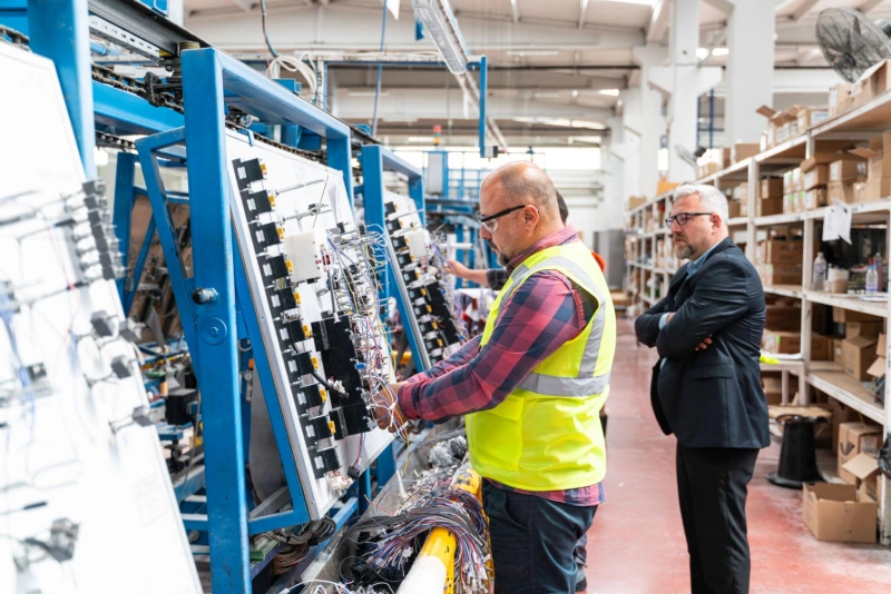
When selecting a cable assembly manufacturer, you should determine whether the supplier can understand your design requirements, possesses the necessary manufacturing processes, is capable of stable mass production, and can trace back to the materials, batches, and versions in the event of a problem.
Engineering Support, Process Capability, Quality System, Capacity, and Traceability
| Evaluation Item | What to Confirm | Common Risk |
|---|---|---|
| Engineering Support | DFM, material selection, and design optimization support. | Supplier only builds to print and misses design risks. |
| Process Capability | Crimping, soldering, shield termination, overmolding, etc. | Critical processes are outsourced or unsupported. |
| Quality System | Incoming, production, inspection, and defect control. | Certificates exist, but process control is inconsistent. |
| Testing Capability | Continuity, insulation, functional, and required tests. | Testing is too limited to cover real risks. |
| Capacity | Ability to scale from prototypes to mass production. | Samples are good, but volume quality or lead time is unstable. |
| Traceability | Material lots, production lots, revisions, and test records. | Affected batches cannot be identified. |
| Change Control | Approval process for material, process, or design changes. | Unapproved substitutions or process changes. |
| Supply Chain | Stable sources for wires, terminals, and connectors. | Single-source dependency or long-term shortages. |
RFQ Package and Supplier Evaluation Checklist
RFQ Package
A common mistake when seeking quotes from cable assembly suppliers is providing too little information in the RFQ.
An RFQ, or Request for Quotation, refers to the documentation you send to suppliers for them to provide quotes and evaluate manufacturability.
A comprehensive RFQ package should, at a minimum, clearly convey to suppliers: what you need done, how it should be done, the quantity required, and the quality and testing specifications.
Common RFQ information includes:
- Drawings
- BOM (Bill of Materials)
- Pinout
- Connector and Terminal Part Numbers
- Wire/Cable Specifications
- Length and Tolerance
- Shielding Requirements
- Overmolding Requirements
- Labeling Requirements
- Electrical Test Requirements
- Environmental Requirements
- Expected Volume
- Prototype Quantity
- Target Production Schedule
Supplier Evaluation Checklist
| Evaluation Item | Questions to Ask |
|---|---|
| DFM Capability | Does the supplier review drawings, BOM, and pinout before quoting and identify manufacturing risks? |
| Key Processes | Which processes are in-house or outsourced? Are critical processes supported by stable equipment and operators? |
| Material Control | Are wire, terminals, connectors, and other key materials changed without approval? |
| Testing Capability | Can the supplier perform required electrical, functional, and project-specific tests? |
| Quality Management | How are first article inspection, in-process inspection, final inspection, and defect handling managed? |
| Traceability | Can the supplier track material lots, production lots, drawing revisions, and test records? |
| Change Control | Do material, design, or process changes require customer approval before implementation? |
| Capacity | Can production scale from prototypes to volume without major changes in equipment, staff, or process? |
| Supply Chain | Are key connectors, terminals, and wires available long term? Is there single-source risk? |
| Documentation | Can the supplier provide CoC, inspection records, test reports, FAI, and other required documents? |
Frequently Asked Questions About Cable Assemblies
Q1: What information is required for a cable assembly quote?
You will need to provide drawings, a BOM, pinout, connector and terminal part numbers, wire/cable specifications, length and tolerances, shielding or overmolding requirements, testing requirements, estimated purchase quantity, and the number of samples. The more complete the information, the more accurate the supplier’s quote will be, and the fewer subsequent price adjustments and rework will be required.
Q2: What affects cable assembly cost?
Key factors include the cost of wire and connectors, length, number of terminals, branching complexity, shielding, overmolding, labeling, testing requirements, assembly difficulty, and order quantity. Special materials, complex processes, small batch sizes, and rigorous testing typically increase costs.
Q3: How long does prototyping and production take?
There is no standard timeframe. The prototype lead time depends on whether materials are in stock, whether custom molds are required, the complexity of the drawings, and testing requirements; mass production lead times are also influenced by order quantity, lead times for critical materials, and factory capacity. When requesting a quote, it is best to ask the supplier to provide separate lead times for prototypes and mass production.
Q4: What tests should appear on a certificate of conformance?
A CoC does not necessarily need to list all specific test results; its primary purpose is to certify that the batch of products complies with the specified drawings, specifications, or procurement requirements. If requested by the customer, the document may specify that tests such as Continuity, Hipot, Insulation Resistance, and Functional Tests have been performed, along with the applicable standards; detailed test data is typically better suited for inclusion in a separate Test Report.
Conclusion: Cable Assembly 101: Design, Process, and Sourcing
By now, this article should have given you a fairly comprehensive understanding of the basic concepts, main types, design requirements, manufacturing processes, testing methods, and supplier selection for cable assemblies.
When selecting a cable assembly, you shouldn’t focus solely on price or the appearance of the connectors. A more reasonable approach is to first clarify your application requirements, then decide whether to use a standard or custom cable assembly, and further confirm that the wire, terminals, connectors, shielding, overmolding, and testing solutions are truly compatible.
As a provider of cable assembly and wire harness solutions, Linkwings can offer support ranging from material selection and DFM evaluation to custom manufacturing based on your drawings, BOM, pinout, application environment, and testing requirements, helping you obtain a connectivity solution that is best suited for your actual product.

Nicole
The founder of Linkwings Electronics.
10+ Years Experience | 1000+ Global Projects Completed
Specialized in:
- Custom Wire Harness Assembly
- Automotive & Industrial Cable Harness Manufacturing
- Precision Crimping & Terminal Processing
- OEM / ODM Wire Harness Solutions
Need help with your project?
Let Linkwingselec deliver your next wire harness solution.