Wire Harness Colors: Car Stereo Color Guide
Home » Wire Harness Colors: Car Stereo Color Guide
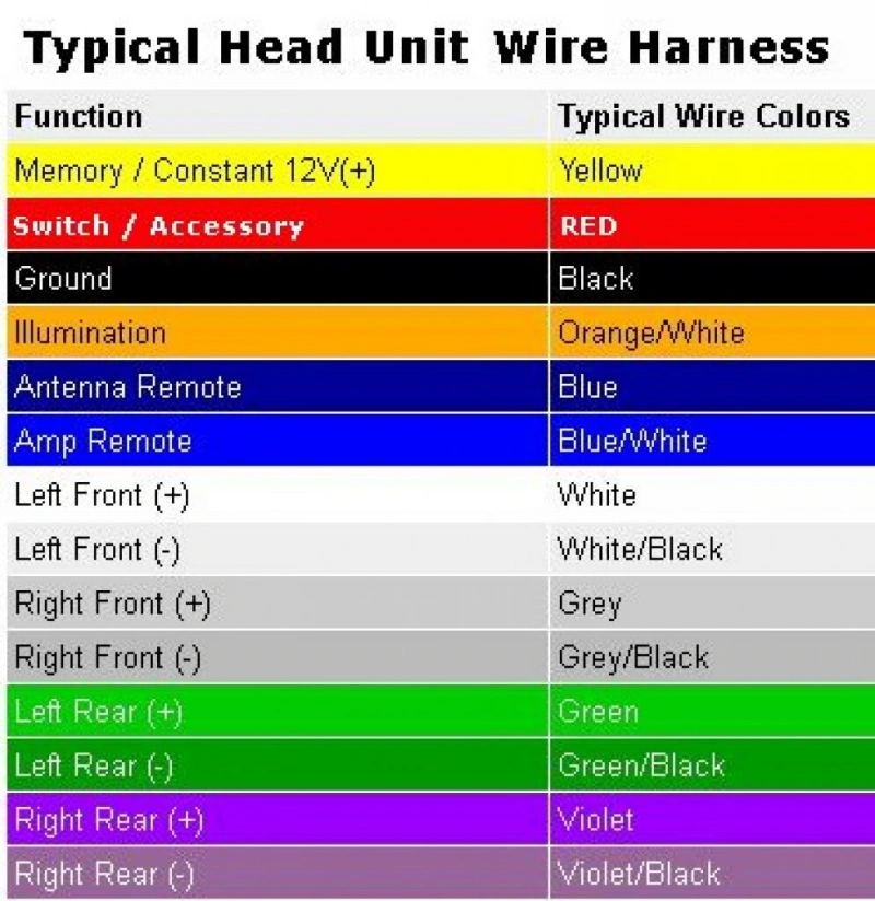
In car audio wiring harnesses, you’ll often see red, yellow, black, and blue wires, as well as pairs of white, gray, green, and purple wires. If you’re installing or replacing a car audio system for the first time, these colors can indeed be confusing.
In common aftermarket car audio wiring harnesses, the colors of many wires actually follow fairly standardized industry conventions. However, it’s important to note that when installing a car audio system, you should never connect wires based solely on color; it’s even more important to verify the actual function of each wire.
This article will use a car stereo wiring color chart to introduce the colors of common power wires, ground wires, amplifier control wires, and speaker wires, and further explain how to verify them using wiring diagrams, harness adapters, pinouts, and a multimeter.
What Do Car Stereo Wire Harness Colors Mean?
The different colors in a car audio wiring harness are primarily used to help you quickly identify the electrical function of each wire.
1. Core Power and Ground Wires
- Yellow: Constant power. This wire remains energized even after the engine is turned off and is primarily responsible for preserving the audio system’s memory settings, such as the time and preset radio stations.
- Red: ACC power. Power is supplied only when the ignition key is turned to the ACC or ON position; this controls the audio system’s operation in tandem with the vehicle’s engine.
- Black: Ground. Provides a path for current to return to the battery’s negative terminal; it is typically connected to an exposed metal part of the vehicle body.
2. Speaker Connections and Positive/Negative Polarity
- Color Correspondence: Pairs of white, gray, green, and purple wires correspond to the front left, front right, rear left, and rear right speakers, respectively.
- Positive/Negative Polarity: Each pair consists of a “solid-color wire + a wire of the same color with black stripes.” The solid-color wire is positive, and the wire with black stripes is negative.
Tip: The positive and negative terminals of the speakers must never be connected in reverse; otherwise, it will result in phase errors, low-frequency attenuation, or a distorted sound field.
3. Amplifier Control and Other Auxiliary Wires
- Blue: Remote turn-on signal. This is not the main power line for the amplifier but rather a control signal that tells an external amplifier or power antenna when to turn on.
- Others: For example, orange is typically used for lighting control, while brown may be used for a mute signal, etc.
Aftermarket Car Stereo Wire Color Chart
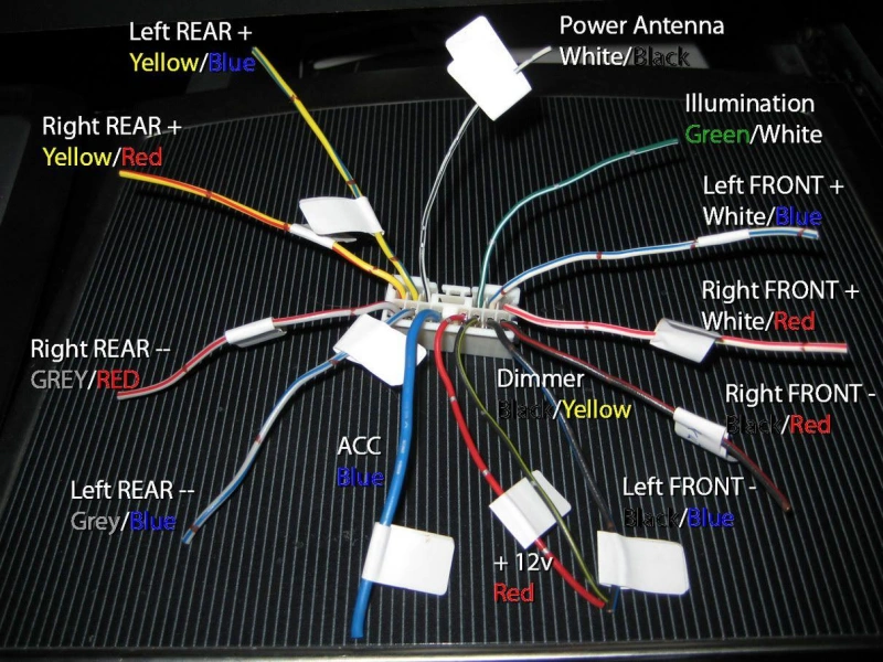
Aftermarket car audio harnesses use a common color-coding system that allows you to quickly identify power, speaker, and control wires. However, it’s important to note that these colors primarily apply to aftermarket stereo harnesses and are not a standardized system for all factory-installed vehicle harnesses.
Before actually connecting the wires, you should still refer to the head unit’s manual, the harness labels, and the pinout specific to your vehicle model.
Power, Accessory, Ground, Illumination, and Remote Wires
| Wire Color | Function | Purpose | Wiring Notes |
|---|---|---|---|
| Yellow | Constant 12V / Battery | Provides continuous power for memory, clock, and settings. | Do not connect to switched ignition power. |
| Red | ACC / Switched 12V | Controls radio power based on ignition status. | Some modern vehicles use CAN signals instead of a direct ACC wire. |
| Black | Ground | Provides electrical return path. | Use a reliable ground point to prevent startup issues or noise. |
| Orange / Orange-White | Illumination / Dimmer | Connects to vehicle lighting or dimming control. | Function may vary by head unit manufacturer. |
| Blue | Power Antenna | Controls an electric antenna. | May only output power during radio mode. |
| Blue-White | Amplifier Remote Turn-On | Activates external amplifiers. | Control signal only, not a power supply for amplifiers. |
Tip: The most common source of confusion here is between the yellow and red wires. The yellow wire ensures that the head unit retains necessary settings even after the vehicle is turned off, while the red wire signals to the head unit that “the vehicle is now ready for operation.” If these two wires are connected in reverse, common issues may include the head unit failing to power on or off properly with the vehicle, or settings being reset every time the engine is turned off.
Front and Rear Speaker Wire Pairs
Speaker wires for aftermarket audio systems use four color groups, corresponding to the left front, right front, left rear, and right rear speakers.
A very important rule to remember is: solid colors indicate the positive terminal, while the same color with a black stripe indicates the negative terminal.
| Speaker Location | Positive Wire (+) | Negative Wire (-) |
|---|---|---|
| Front Left | White | White / Black |
| Front Right | Gray | Gray / Black |
| Rear Left | Green | Green / Black |
| Rear Right | Purple | Purple / Black |
The key here is to ensure that the polarity of all speakers is consistent. If one speaker is connected backwards while the others are connected correctly, you may still hear sound, but there could be a phase mismatch between the speakers, which will affect low-frequency performance and soundstage localization.
When wiring, don’t just connect the wires randomly because “they both look like speaker wires”; instead, you should verify two things: the speaker’s position and its polarity.
Parking Brake, Reverse, Steering-Wheel Control, and Other Leads
In addition to the basic power, ground, and speaker wires, aftermarket head units equipped with touchscreens, backup cameras, navigation, or steering wheel controls may also include auxiliary signal wires.
The color consistency of these wires is much lower than that of basic power and audio wires, so you cannot rely solely on color to identify them. Below are the functions and key wiring considerations for common auxiliary signal wires:
| Wire Name | Common Color Examples | Function | Key Notes |
|---|---|---|---|
| Parking Brake | Light green (varies by model) | Detects parking brake status. | Check the head unit manual. Do not identify by color only. |
| Reverse / Back-Up | Purple/White (varies by model) | Detects reverse gear for automatic camera switching. | Connect to the correct reverse signal, not random 12V power. |
| Steering-Wheel Control | Brown, Brown/White, Key1, Key2, etc. | Controls audio functions from steering wheel buttons. | Vehicle and head unit requirements vary. A dedicated interface may be required. |
| Mute | Not standardized | Mutes the head unit through external devices. | Connect only when this function is required. |
| Speed / VSS | Not standardized | Provides vehicle speed signal. | Used by some navigation or advanced systems. Do not connect to power wires. |
| Camera Power / Trigger | Not standardized | Related to rear camera power or trigger signals. | Camera power and reverse trigger are different signals. |
| Microphone / USB / Data Leads | Usually not identified by wire color | Handles microphone, USB, or data communication. | Use dedicated connectors. Do not identify by voltage testing. |
Key Points for Core Wiring
Parking Brake: The head unit uses this to determine whether the vehicle is in a state that allows certain functions to be operated. Detection logic may vary by head unit, so do not assume that a light green wire is the parking brake wire just because of its color.
Reverse: Used to signal to the head unit that “the vehicle is in reverse gear,” triggering the automatic switch to the reverse camera view. It is important to distinguish between the reverse trigger signal and the camera power supply—they are not the same circuit. The former informs the head unit when the vehicle is in reverse gear, while the latter provides operating voltage to the camera.
Steering-Wheel Control: This is the most complex part. Older or simpler systems may use resistive analog signals, while many modern vehicles transmit steering wheel button information via data networks such as the CAN bus. In such cases, a dedicated protocol adapter module is required to convert the signals.
Are Wire Harness Colors the Same in Every Vehicle?
No. Car wiring harness colors are not the same across all vehicle models.
You can divide car audio wiring into two categories: aftermarket wiring and factory wiring (original vehicle wiring). Aftermarket audio systems use a relatively consistent color-coding system to facilitate installation; however, factory wiring harnesses are designed by each automaker and may vary across different brands, models, model years, and trim levels.
Tip: The rule of thumb that “red is ACC, yellow is power, and black is ground” is primarily intended to help you identify wiring harnesses for aftermarket head units; it cannot be directly applied to a vehicle’s factory connectors.
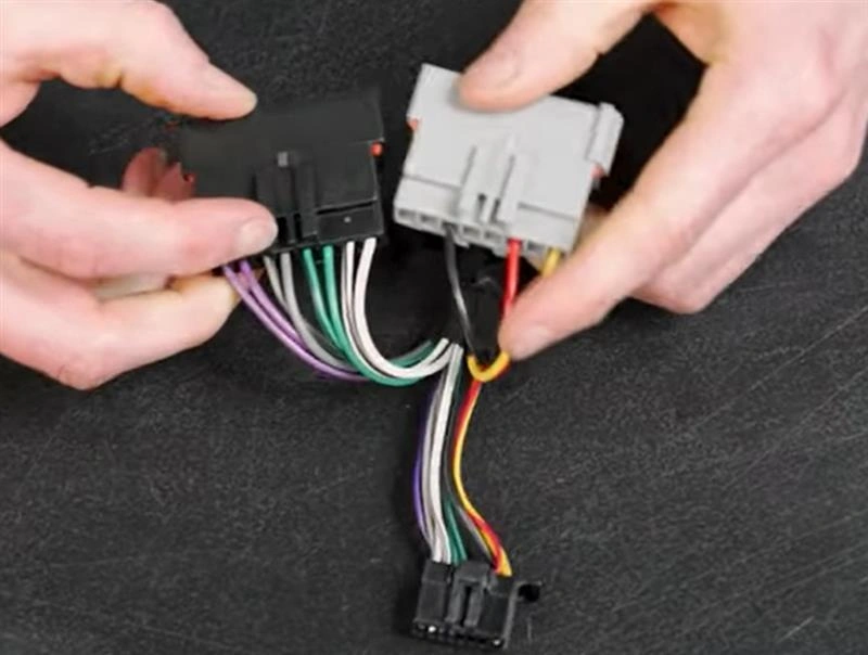
Aftermarket Standards vs. Factory Wiring
Aftermarket Wiring Harnesses:
Definition: Refers to wiring harnesses used with aftermarket head units, adapter harnesses, or third-party audio systems.
Features: To facilitate cross-brand installation, many aftermarket products adopt similar color-coding conventions. For example, yellow is often used for constant 12V power, red for ACC, black for ground, and white, gray, green, and purple for the four speaker groups.
Advantages: High color consistency allows for quicker identification of each wire’s function when replacing an aftermarket head unit with a different brand.
OEM Wiring Harnesses:
Definition: Wiring defined by the automaker during the vehicle’s design phase.
Characteristics: Factory engineers determine wire colors based on the vehicle platform, electrical architecture, connector design, and production requirements. Different manufacturers—and even different models from the same brand—may assign completely different functions to the same color.
Risks: For example, while a yellow wire on an aftermarket head unit typically indicates constant power (12V), a yellow wire in a vehicle’s factory connector could represent power, a control wire, a signal wire, or another circuit; aftermarket conventions must never be applied directly.
Logic for Identifying Different Wiring Harnesses
When dealing with wiring harnesses from different sources, different verification strategies should be adopted:
| Harness Type | Can Color Be Trusted? | Correct Approach |
|---|---|---|
| Aftermarket Head Unit Harness | Yes, usually reliable. | Confirm with the head unit manual. |
| Aftermarket Adapter Harness | Usually useful as a reference. | Check harness labels and documentation. |
| Factory Vehicle Harness | No, color alone is not enough. | Use vehicle wiring diagrams and pinout information. |
| CAN Bus Vehicles | No, do not rely on wire color. | Confirm whether a CAN Bus interface module is required. |
Tip:During actual installation, if you are working with the original wiring harness, the safest approach is to consult the wiring diagram for your specific vehicle model or use a dedicated adapter harness designed for that model. Be sure to verify functionality with a multimeter before making any connections.
Why Model, Trim, Amplifier, and Year Matter
| Factor | Possible Changes | Why It Matters | How to Confirm |
|---|---|---|---|
| Model | Different connectors, pin locations, and signal definitions. | Same brand does not always mean the same audio harness. | Check the exact vehicle model, wiring diagram, or pinout. |
| Trim Level | Differences in speakers, subwoofer, navigation, steering controls, and cameras. | Different trims may use different harnesses and functions. | Confirm vehicle trim and factory audio system type. |
| Factory Amplifier | May use low-level or digital audio signals instead of direct speaker output. | Incorrect wiring can cause no sound, low volume, or amplifier issues. | Check for a factory amplifier and whether an adapter is required. |
| Year | Connectors, electrical architecture, or control systems may change. | Vehicles with similar appearances can have different audio interfaces. | Search by exact model year, not vehicle name only. |
| CAN Bus / Vehicle Network | ACC, steering controls, and amplifier signals may use data communication. | Some functions may not have dedicated wires for direct connection. | Confirm CAN Bus usage and whether an interface module is needed. |
How Do You Verify a Wire Before Connecting It?
When wiring a car audio system, you should first verify the actual function of the wire. You can think of the verification process as follows: first, consult reference materials; then, check the pin assignments; and finally, use a multimeter to confirm the electrical status.
The reason for this is that factory wiring harnesses may vary depending on the vehicle model, model year, and configuration. Additionally, modern vehicles may include data or control lines such as CAN bus, factory amplifiers, and steering wheel controls.
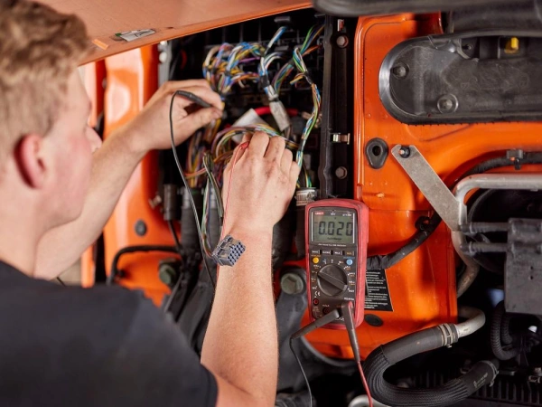
Use the Vehicle Diagram, Harness Adapter, Pinout, and Multimeter
When wiring a car audio harness, the key principle is “first verify the function, then match the colors.”
1. Vehicle Wiring Diagram: A Reliable Reference
Key Role: The wiring diagram is the most authoritative resource for determining circuit functions; it clearly labels the specific routing and connection points for each wire and pin within a connector.
Practical Requirements: Before installation, you must consult the original factory repair manual or official wiring diagrams for the specific vehicle model to confirm the exact locations of the power supply, ground, speakers, and data bus. Never wire blindly without referring to the diagrams.
2. Vehicle-Specific Wiring Harness Adapters: The Top Choice for Non-Destructive Installation
Key Function: The adapter converts the vehicle’s original factory connector into a standard interface for aftermarket audio systems, eliminating the need to cut the original wiring harness and identify each wire individually.
Practical Requirements: Prioritize using adapters that are specifically matched to the vehicle’s make, model, year, and audio configuration. These adapters not only convert the physical connector but also use internal protocol modules to convert complex factory signals into standard connection formats recognizable by aftermarket head units.
3. Pinout: Physical Location Determines Function
Core Function: Pinout refers to the specific function assigned to each pin in a connector.
Practical Requirements: Even if two wires are exactly the same color, their functions can differ drastically if their pin positions are different. When wiring, you must strictly follow the pinout diagram.
4. Multimeter: The Final Verification Tool
Core Function: When documentation cannot provide complete confirmation, a multimeter is used to measure voltage, resistance, and continuity; it is the most practical tool for verifying the power, ACC, and ground circuits.
Practical Requirements: The purpose of a multimeter is to confirm whether the actual vehicle status matches the wiring diagram, not to speculate on the entire wiring system.
Safe Testing Sequence and Battery Precautions
1. Eight-Step Standard Safety Testing Process
Step 1: Confirm the vehicle model, model year, and audio system configuration.
Step 2: Consult the wiring diagram and pinout.
Step 3: Turn off the vehicle and inspect the connectors.
Step 4: Check whether the bare wires have been insulated.
Step 5: Restore power to the vehicle when necessary.
Step 6: Use a multimeter to verify Constant, ACC, and Ground.
Step 7: Turn off the power again and complete the final wiring.
Step 8: Check that all unused wires are insulated.
2. Battery Precautions
- Be sure to consult the repair manual before disconnecting the battery: do not simply assume that “all tests require disconnecting the battery first.”
- Never test unknown circuits by force: When dealing with circuits whose nature cannot be confirmed, do not touch bare wires together, apply 12V directly, or ground them just to “see what happens.”
- Core principle: First, use the manual to confirm “what it should be”; then, use a multimeter to verify “whether it actually is that way”; only then proceed with wiring. Verify the wire’s actual electrical function, not its color.
How Do You Connect an Aftermarket Stereo Harness?
When connecting an aftermarket stereo harness, the most important rule is to connect wires with the same function together.
A safe procedure is as follows: First, identify the function of each wire on both the vehicle side and the new head unit side; then, select the appropriate connection method; and finally, verify that the factory data bus, amplifier, and auxiliary functions have not been incorrectly bypassed or shorted.
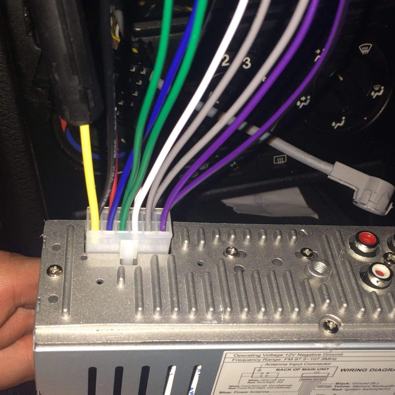
Match Functions, Not Colors Alone
The wire colors in aftermarket head unit harnesses generally follow a consistent pattern; for example, yellow is often used for Constant 12V, red for ACC, black for Ground, and white, gray, green, and purple for speakers.
However, when actually wiring the system, the correct method is to first identify the function of each wire and then match them one by one.
| Head Unit Function | Required Vehicle / Harness Connection |
|---|---|
| Constant 12V | Continuous battery power supply. |
| ACC / Switched 12V | Ignition-controlled power signal or interface output. |
| Ground | Reliable vehicle ground connection. |
| Front Left Speaker | Front left speaker positive and negative wires. |
| Front Right Speaker | Front right speaker positive and negative wires. |
| Rear Left Speaker | Rear left speaker positive and negative wires. |
| Rear Right Speaker | Rear right speaker positive and negative wires. |
| Amplifier Remote | Factory or external amplifier turn-on input. |
| Reverse Trigger | Correct reverse gear signal. |
| Steering-Wheel Control | Compatible control interface or adapter module. |
Please note that the colors of the factory-installed wiring harness may not match those of the aftermarket head unit.
Crimp, Solder, Heat-Shrink, and Connector Options
Once the functionality has been verified, selecting a reliable wiring method is key to ensuring the long-term, stable operation of the car audio system.
Crimping
Key Advantages: When crimped correctly, it offers excellent mechanical strength, making it suitable for automotive environments subject to continuous vibration and bending.
Practical Tips: It is essential to ensure that the crimp terminal, wire gauge, and crimping tool are strictly matched. If the wire is too thin, the crimp will not hold securely; if it is too thick, it will not insert properly.
Quality Verification: After crimping, a pull test must be performed to confirm that the wire will not slip out of the terminal easily.
Soldering
Key Advantages: Creates an excellent electrical connection with extremely low contact resistance.
Potential Risks: If solder penetrates too deeply into the wire, it can cause localized hardening of the otherwise flexible stranded wire. In areas subject to continuous vibration or bending, this rigid transition zone is highly prone to becoming a stress concentration point, leading to breakage.
Practical Recommendations: When using soldering, avoid creating excessively long or hard soldered areas, and ensure proper insulation and mechanical support after completion.
Heat-Shrink Tubing
Core Purpose: Heat-shrink tubing is not a connection method in itself, but rather serves to protect completed connections by providing insulation, stress relief, and mechanical protection.
Selection Recommendations: If the connection point may be exposed to moisture, double-wall heat-shrink tubing with a hot-melt adhesive layer or sealed crimp terminals must be used; single-wall tubing is sufficient for standard applications behind the in-vehicle head unit.
Tip: Do not use heat-shrink tubing to “cover up” a poor-quality connection. The connection itself must be reliable first; heat-shrink tubing is only for subsequent protection.
Connector Options:
Preferred Solution: Prioritize using plug-in wiring harness adapters or pre-assembled wiring harnesses with connectors.
Key Advantages: No need to cut the original factory wiring harness directly; wiring definitions are clearer; and subsequent repairs, head unit replacements, or restoration to factory condition are extremely convenient.
Protect Data-Bus and Factory-Amplifier Circuits
1. Data Bus
Core Function: Data networks such as the CAN bus serve as the hub for communication among various electronic modules in modern vehicles. The factory head unit is not only responsible for playing music but also plays a key role in functions such as determining ACC status, controlling steering wheel buttons, accessing vehicle settings menus, outputting/warnings, controlling the factory amplifier, and triggering reverse gear and camera functions.
Identification Characteristics: If the factory connector contains paired twisted-pair wires, or if the wiring diagram is labeled with terms such as “CAN High,” “CAN Low,” “Data,” or “Bus,” it is a data bus.
Tip: Do not treat data wires as ordinary 12V wires. Do not apply 12V directly to data wires, ground them directly, short-circuit two bus wires arbitrarily, or test unknown wires one by one in an attempt to “locate the ACC.”
2. Factory Amplifier
Signal Conversion: If the vehicle is equipped with a factory-installed independent amplifier, there are typically no traditional four-speaker output wires behind the head unit. Instead, there may be low-level audio signals, differential audio signals, digital audio signals, amplifier power-on control wires, or data bus control signals.
Wiring Mistakes: Simply connecting the aftermarket head unit’s speaker outputs directly to the factory wiring will not only result in no sound but may also cause equipment failure due to impedance mismatch with the signal input.
Verification Steps: First, determine whether the factory speakers are driven directly by the head unit or by a separate amplifier; if a separate amplifier is present, you must confirm the required input signal type and whether a dedicated factory amplifier retention interface is needed.
Why Does a Stereo Fail After Wiring?
If your car audio system doesn’t work after the wiring is complete, it doesn’t necessarily mean the head unit itself is damaged. Common causes include an incorrect connection in one of the following areas: power supply, ground, ACC, speaker polarity, amplifier control, or the factory interface.
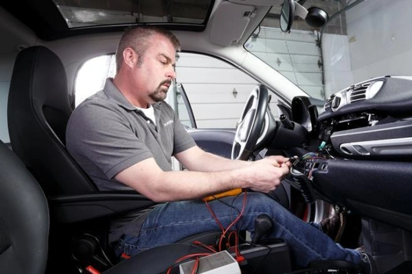
No Power, Memory Loss, Noise, Reversed Speakers, and No Amplifier Output
When troubleshooting aftermarket car audio installations, the core principle is to “check the power supply first, then the audio signal.”
No Power
- Key Troubleshooting Steps: Check the power supply first, rather than the speaker wiring.
- Common Causes: Constant power or ACC not properly connected; blown fuse in the head unit or vehicle; corroded or faulty ground connection.
- Special Case: Some modern vehicles provide ignition status via a data bus; without the correct vehicle-specific interface module, the head unit will be unable to receive the power-on signal.
Memory Loss
- Typical Symptoms: Every time the vehicle is turned off, the head unit’s time, preset radio stations, or personalized settings are automatically reset.
- Root Cause: The Constant 12V power supply is not continuous, or the yellow constant power wire and the red ACC wire are incorrectly reversed.
- Troubleshooting Focus: With the vehicle completely turned off, use a multimeter to measure the head unit’s constant power input to confirm whether it maintains a stable 12V voltage.
Noise
- Typical Symptoms: The audio system produces a humming or screeching sound, or the noise varies with engine RPM.
- Common Causes: Poor ground connection; electromagnetic interference caused by routing audio signal wires parallel to high-current power lines; a ground potential difference between an external amplifier and the head unit; or incorrect connection at adapter interfaces.
Tip: Do not simply assume that “adding a thicker ground wire will definitely solve the problem.” First, verify that the head unit and amplifier are securely grounded, and determine whether the noise occurs on all input sources or only on specific inputs.
Reversed Speakers
- Typical Symptoms: This does not result in complete silence but distorts the soundstage. Symptoms include noticeably weaker bass, scattered sound, and a lack of focus.
- Physical Principle: When one set of speakers is connected correctly (positive to positive, negative to negative) and another set is connected in reverse, the sound waves emitted by the two sets of speakers will cancel each other out at specific frequencies.
- Troubleshooting Focus: You must verify that each set of speakers strictly follows the “positive to positive, negative to negative” connection logic, rather than simply confirming that “these two wires belong to the same speaker.”
No Amplifier Output
- Typical Symptoms: The head unit powers on and lights up normally, but there is absolutely no sound from the speakers. This is extremely common in vehicles equipped with an external amplifier or a factory-installed amplifier.
- Basic Troubleshooting: Verify that the Remote Turn-on wire is properly connected. This wire tells the amplifier when to turn on; if it is not connected, the amplifier will remain off at all times.
- Factory Amplifier Systems: The issue is more complex. Factory amplifiers may require specific analog signals, differential signals, digital audio, or data bus control.
Diagnostic Checklist by Symptom
| Problem | First Checks | Common Causes | How to Diagnose |
|---|---|---|---|
| Head Unit Does Not Power On | Constant 12V, ACC, Ground, Fuse | Missing power, incorrect ACC, poor ground, or blown fuse. | Use wiring diagrams and a multimeter to verify power and ground. |
| Settings Lost After Ignition Off | Constant 12V | No continuous power or incorrect Constant/ACC connection. | Check if the memory wire still has power after vehicle shutdown. |
| Head Unit Does Not Follow Vehicle Power | ACC / Data Interface | Incorrect ACC connection or CAN Bus-controlled vehicle system. | Confirm whether the vehicle has a traditional ACC wire. |
| No Sound From All Speakers | Amplifier, Remote, Audio Interface | Amplifier not activated or factory amplifier incompatibility. | Check whether the amplifier receives the correct turn-on signal. |
| One Speaker Has No Sound | Speaker wires and connection points | Broken wire, loose connection, or incorrect pin assignment. | Check the specific channel wiring against the pinout. |
| Weak Bass or Abnormal Sound | Speaker polarity | Speaker positive and negative wires reversed. | Verify polarity of all speaker wire pairs. |
| Constant Noise or Humming | Ground, signal cables, amplifier ground | Poor grounding, interference, or connection issues. | Check whether noise changes with engine speed, volume, or input source. |
| Amplifier Does Not Turn On | Remote Turn-On | Blue-white remote wire disconnected or incorrect output. | Check if the amplifier remote terminal receives the correct signal. |
| Steering Controls or Vehicle Alerts Lost | Data Interface Module | Vehicle functions depend on CAN Bus or dedicated interfaces. | Verify the vehicle interface is installed and configured correctly. |
| Reverse Camera Does Not Switch Automatically | Reverse Trigger | Incorrect reverse signal connection. | Confirm the head unit receives the correct reverse status signal. |
When Should You Use a Vehicle-Specific Harness Adapter?
When installing an aftermarket stereo in your vehicle, unless the stock system is a very basic, traditional audio system, you should prioritize using a vehicle-specific harness adapter.
Its purpose is to help you convert the vehicle’s existing power, speaker, control, and data functions into interfaces compatible with the aftermarket head unit—without having to cut the factory wiring harness.
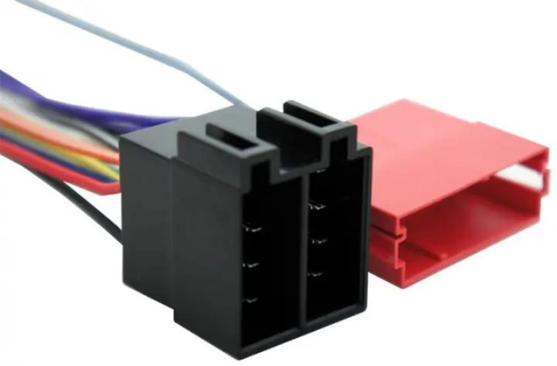
Retaining Steering Controls, Chimes, Cameras, and Factory Amplifiers
When upgrading a car’s audio system through an aftermarket installation, the ability to fully preserve the vehicle’s original electronic functions is a key criterion for evaluating the professionalism of the modification plan.
1. Steering Wheel Control Protocol Conversion
Signal Logic: In modern vehicles, steering wheel buttons may no longer use simple, independent switch wires but instead transmit signals to the factory head unit via resistive signals or data buses.
Solution: Simply replacing the head unit with an aftermarket model may cause the buttons to stop working. It is necessary to use a steering wheel control interface module compatible with both the vehicle model and the aftermarket head unit to convert the vehicle’s control signals into a format recognizable by the aftermarket head unit.
2. The Link Between Alert Tones and Driving Safety
Output Mechanism: On many vehicle models, safety or status alert tones are not generated by a separate buzzer but are output directly through the factory audio system.
Note: If the corresponding interface is not retained when replacing the head unit, the alert tones will disappear entirely, posing a safety hazard. If the compatibility documentation indicates that the chime is linked to the factory audio system, you must select a model-specific interface that supports this feature; simply purchasing basic power and speaker adapter cables is insufficient.
3. Differences in Factory Camera Interfaces
Compatibility Challenges: The power supply voltage, video interface standards, and reverse trigger methods of factory-installed cameras often do not fully match those of aftermarket head units. Aftermarket head units require standard video inputs and a dedicated reverse trigger, whereas factory systems may manage cameras via proprietary connectors or the vehicle’s onboard network.
Practical Requirements: You cannot simply connect the vehicle’s existing wires directly to the new head unit and expect it to work. You must verify the factory camera’s video signal type, power supply method, and reverse trigger logic. If necessary, use a dedicated camera retention adapter to perform signal conversion.
4. Signal Matching for Factory Amplifiers
Key Differences: In vehicles equipped with a dedicated factory amplifier, the head unit typically does not drive the speakers directly but instead outputs an audio signal to the amplifier. The input formats for factory amplifiers are complex and may include low-level audio, differential signals, or even rely on digital communication or the vehicle data bus.
Solution: The aftermarket head unit’s four speaker outputs cannot be directly connected to the vehicle’s original wiring harness. Typically, a factory amplifier retention interface is required to allow the new head unit to properly drive or control the factory amplifier.
Frequently Asked Questions About Wire Harness Colors
Q1: What do the red and yellow stereo wires do?
In common aftermarket audio wiring harnesses, the red wire is typically the ACC / Switched 12V (controlled power) wire, used to turn the head unit on or off based on the vehicle’s power status; the yellow wire is typically the Constant 12V (constant power) wire, used to provide continuous power and preserve settings such as time and presets. Actual wiring should still be based on the head unit’s manual and the vehicle’s wiring diagram.
Q2: Which wire turns on the amplifier?
It is usually the blue/white Remote Turn-On wire. It sends a power-on signal to an external amplifier, but it is not the amplifier’s main power line and cannot be used to directly power the amplifier.
Q3:What does a black stripe mean on speaker wires?
In common aftermarket audio harnesses, speaker wires with a black stripe on the same-colored wire typically indicate the negative terminal. For example, white might be the positive terminal for the left front speaker, while white-black is typically the negative terminal for the left front speaker.
Q4: Can unmatched wires be left disconnected?
Yes, but only if you have confirmed that the function associated with that wire is not needed. Unconnected wires should be insulated separately and secured to prevent exposed conductors from coming into contact with the vehicle body or other wiring. For CAN Bus, factory amplifiers, or other unknown wiring, do not disconnect them arbitrarily until their function has been confirmed.
Conclusion: Wire Harness Colors: Car Stereo Wiring Chart and Guide
Overall, understanding the colors of car audio wire harnesses isn’t just about memorizing “what the red, yellow, and black wires represent”; more importantly, it helps you correctly identify power, ground, speaker, amplifier control, and other auxiliary lines, preventing wiring errors that could cause the head unit to fail to start, settings to be lost, noise, speaker malfunctions, or the loss of factory features.
If you’re looking for reliable car audio wire harnesses, vehicle-specific harnesses, or custom wire harness solutions, learn more about Linkwings. Through proper harness design, connector matching, and functional definition, you can reduce installation errors, improve system reliability, and simplify future maintenance and upgrades.

Nicole
The founder of Linkwings Electronics.
10+ Years Experience | 1000+ Global Projects Completed
Specialized in:
- Custom Wire Harness Assembly
- Automotive & Industrial Cable Harness Manufacturing
- Precision Crimping & Terminal Processing
- OEM / ODM Wire Harness Solutions
Need help with your project?
Let Linkwingselec deliver your next wire harness solution.