Coaxial Cable Types: How to Pick the Right One for Your Application
Home » Coaxial Cable Types: How to Pick the Right One for Your Application
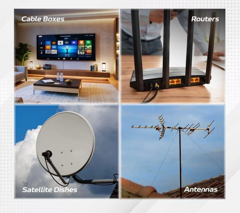
Coaxial cables are widely used in systems such as television, CCTV surveillance, broadband networks, RF (radio frequency), GPS, cellular communications, Wi-Fi antennas, and test equipment.
Different types of coaxial cables actually vary significantly in terms of characteristic impedance, signal attenuation, operating frequency, power handling capacity, shielding performance, wire diameter, and flexibility.
Starting with the internal structure of coaxial cables, this article provides a systematic overview of common types—including the RG6, RG59, RG11, RG58, RG8, RG213, and LMR series, as well as semi-rigid, micro-coax, and Twinax cables—and explains how to select connectors and the logic behind choosing the right cable for different applications. This will help you more accurately select the coaxial cable best suited for your project.
What Is a Coaxial Cable and How Is It Built?
Coaxial cable is a type of cable specifically designed to transmit high-frequency electrical signals. It consists of four key components: the center conductor, the dielectric layer, the shielding layer or outer conductor, and the outer jacket. These four components are not merely mechanical structures; together, they determine the cable’s characteristic impedance, signal attenuation, shielding performance, flexibility, and operating frequency range.
Center Conductor, Dielectric, Shield, and Jacket
Coaxial cable consists of four layers from the inside out, each with a distinct function, and must be designed as an integrated system:
Center Conductor:
Responsible for transmitting the core electrical signal. Common materials include solid copper, aluminum-clad copper, and silver-plated copper; it can have either a solid or multi-strand twisted structure.
Dielectric Layer:
Serves as insulation and maintains the spacing between the center conductor and the shielding layer. Its dielectric constant directly affects signal propagation speed, characteristic impedance, and dielectric loss.
Shielding Layer:
Also known as the outer conductor, it provides a return path for signals while containing internal electromagnetic fields, reducing external interference, and minimizing internal signal radiation.
Outer Sheath:
Primarily protects the internal structure from abrasion, moisture, UV radiation, chemicals, and mechanical damage. Different applications—such as indoor wiring, outdoor antenna feedlines, and equipment patch cords—have varying requirements for the sheath’s weather resistance and flame retardancy; cables cannot be interchanged based solely on electrical parameters.
How Construction Affects Impedance and Loss
The structure of coaxial cable determines its characteristic impedance and signal attenuation.
Impedance is determined by a combination of “geometric dimensions and dielectric”: Characteristic impedance is not determined solely by the resistance of the conductor, but rather by the ratio of the center conductor’s diameter to the inner diameter of the outer conductor, as well as the dielectric constant of the intermediate dielectric layer.
Attenuation primarily results from “conductor loss + dielectric loss”: Conductor loss occurs because, at high frequencies, current concentrates on the surface of the conductor, increasing its effective resistance; the higher the frequency, the greater the loss. Dielectric loss, on the other hand, is the energy loss that occurs as an electric field propagates through the insulating layer; it is linearly proportional to frequency and often becomes the dominant factor in high-frequency applications at the GHz level and above.
Trade-offs between wire gauge and structure: For similar structures, a thicker wire gauge results in larger conductor dimensions, which may lead to lower attenuation per unit length. However, when selecting a cable, mechanical factors such as installation space, minimum bend radius, and flexibility must be comprehensively evaluated.
What Are the Main Coaxial Cable Types?
Coaxial cable is not a single product but rather a broad category of transmission lines with a coaxial structure. The names commonly found on the market—such as RG6, RG59, RG11, RG58, RG213, LMR, Semi-Rigid, and Micro-Coax—essentially describe coaxial cables with different structures, sizes, and intended applications.
Tip: Designations such as “RG6” or “RG58” only help you quickly identify a general category and are not a substitute for a complete product datasheet. Cables of the same type produced by different manufacturers may vary in terms of the central conductor, dielectric, shielding, jacket, and high-frequency performance; therefore, when making a formal selection, you should refer to the datasheet for the specific part number.
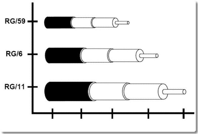
RG6, RG59, and RG11 for 75-Ohm Systems
| Type | Impedance | Key Features | Best For | Limitations |
|---|---|---|---|---|
| RG59 | 75Ω | Thin, light, flexible | Short video runs, CCTV, tight spaces | Higher loss than RG6 and RG11 |
| RG6 | 75Ω | Balanced size, loss, and installation | CATV, broadband, satellite, video | Specs vary by manufacturer |
| RG11 | 75Ω | Thicker, lower-loss design | Longer 75Ω runs | Heavier, stiffer, larger bend radius |
RG58, RG8, RG213, and LMR-Style 50-Ohm Cables
| Type | Impedance | Key Features | Best For | Limitations |
|---|---|---|---|---|
| RG58 | 50Ω | Thin, flexible, easy to terminate | Short RF jumpers, lab equipment, low-power links | Higher loss at high frequencies and long runs |
| RG8 | 50Ω | Thicker than RG58, lower loss | RF, radio, antenna feed lines | Specs vary widely; check the exact cable datasheet |
| RG213 | 50Ω | Large size, lower loss, higher power capability | RF systems, radio, longer antenna feeds | Heavy, stiff, needs more space and bend radius |
| LMR-Style | 50Ω | Low loss with good flexibility | Wi-Fi, cellular, base stations, long RF feeds | LMR is a Times Microwave product family; verify exact or equivalent specs |
Semi-Rigid, Conformable, Twinaxial, and Micro-Coax
These four types of coaxial cables with special structures are all designed to strike a balance between specific mechanical constraints and high-frequency performance. They can be summarized as follows:
Semi-Rigid Coaxial Cable
The outer conductor consists of a continuous metal tube, ensuring an extremely stable geometric relationship between the inner and outer conductors. As a result, it offers excellent shielding performance, high impedance consistency, and easy control of high-frequency performance, making it ideal for microwave and high-frequency RF applications. The drawback is that repeated bending can damage the structure, so it is only suitable for fixed-installation RF modules, test instruments, and microwave components—not for cable harnesses that require frequent movement.
Formable Coaxial Cable
The outer conductor consists of a tin-filled braided layer or a soft metal structure. Its electrical performance is similar to that of semi-rigid coaxial cable, but it can be bent and shaped by hand without specialized tools, making it suitable for complex internal RF routing within equipment. However, it is intended to be “shaped during installation and then used in a fixed position”; it is not designed for continuous dynamic bending and is prone to deformation with prolonged, repeated movement.
Twinaxial Cable
The main difference from standard coaxial cable is that it contains two signal conductors housed together within a shielding structure, making it naturally suited for transmitting differential signals. It is commonly used in high-speed digital communications and high-speed interconnect systems, with typical differential impedances of 85 Ω, 92 Ω, 95 Ω, 100 Ω, 120 Ω, and so on.
Tip:Twinax is not simply “two 50Ω coaxial cables glued together.” The two conductors and the shield are designed as an integrated unit; the spacing between the conductors, the dielectric, and the shield collectively determine the differential impedance and signal integrity. It cannot be simply replaced with two standard coaxial cables.
Micro-Coaxial
Essentially, this is still a coaxial structure, but on an extremely small scale. It is commonly used inside high-density electronic devices, for high-speed inter-board connections, in small antennas, or inside precision instruments. Its advantages include small size, high wiring density, and good flexibility, enabling the transmission of high-speed or RF signals with controlled impedance in confined spaces.
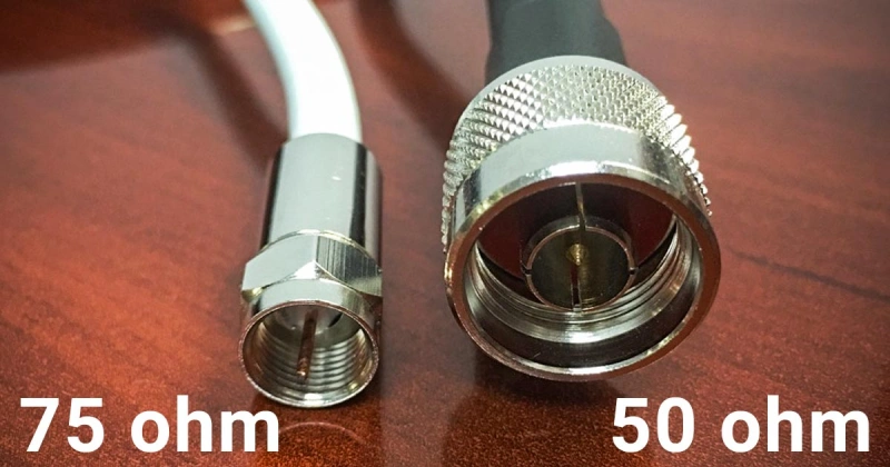
What Is the Difference Between 50-Ohm and 75-Ohm Coax?
The difference between 50Ω and 75Ω coaxial cable cores lies in their different characteristic impedances.
You can think of characteristic impedance as the electrical behavior of the cable when high-frequency signals propagate along it. It is primarily determined by the dimensions of the inner conductor, the outer conductor, and the material of the dielectric, rather than the DC resistance measured with a multimeter.
When choosing between 50Ω and 75Ω, the most important principle is to consider the original design impedance of the entire system.
RF Power, Data, Video, and Test Applications
| Application | Impedance | Typical Uses | Why It Is Used | Selection Notes |
|---|---|---|---|---|
| RF / Wireless | 50Ω | Antennas, Wi-Fi, cellular, radio, RF amplifiers | Balances RF transmission and power handling | Keep cables, connectors, antennas, and ports at 50Ω |
| RF Test | 50Ω | Signal generators, spectrum analyzers, VNAs | Most RF test systems use 50Ω interfaces | Verify the actual port impedance |
| Broadcast Video | 75Ω | SDI, professional video, broadcast systems | Designed for low-loss video transmission | Keep camera, BNC, coax, and video input at 75Ω |
| CATV / TV | 75Ω | Cable TV, television, broadband networks | Standard impedance for TV and CATV systems | Do not substitute 50Ω coax just because it fits |
| Video / 75Ω Test | 75Ω | Video and CATV testing | Matches the impedance of the 75Ω system under test | Not all test equipment is 50Ω; check specifications |
What Happens When Impedance Is Mismatched?
The key consequences of coaxial cable impedance mismatch and the key considerations for selection can be summarized as follows:
Key Hazard: Causes signal reflection, leading to mismatch loss
When a signal encounters a point of impedance discontinuity, some of the energy cannot continue to propagate forward but is reflected back to the signal source. This directly results in mismatch loss, reducing the effective power that actually reaches the load.
High-Power Scenarios: Reflected Energy May Burn Out Equipment
In high-power systems such as RF transmitters and power amplifiers, severe impedance mismatch causes a large amount of reflected power to flow back to the transmitter, resulting in a sharp rise in the junction temperature of power transistors, a shortened device lifespan, and even the direct breakdown and destruction of the power amplifier module.
Video and High-Speed Data Applications: Severe Deterioration of Signal Integrity
In analog video, reflected waves can cause image ghosting or moiré patterns; in high-speed digital communications, reflections can lead to overshoot, undershoot, ringing, and timing jitter, which in turn result in increased bit error rates, eye diagram closure, or even communication failure.
How Do Coaxial Cable Types Compare?
When comparing different coaxial cables, you can’t just look at whether they’re “50Ω or 75Ω” or “what the RG number is.” What truly determines whether a coaxial cable is suitable for your project is whether it strikes the right balance between attenuation at the target frequency, power handling capacity, outer diameter, flexibility, shielding, propagation speed, and environmental rating.
To determine the right cable, first identify your system’s frequency, length, and acceptable loss, then evaluate the power, space, and environmental conditions.
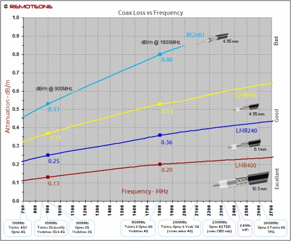
Frequency Range, Attenuation, Power Handling, Diameter, and Flexibility
| Parameter | What to Check | General Rule | Most Important For | Common Mistake |
|---|---|---|---|---|
| Frequency Range | Maximum operating frequency | Higher frequencies demand better dielectric, shielding, and connectors | Microwave, GHz RF, high-speed test systems | Assuming all 50Ω or 75Ω cables support the same frequency |
| Attenuation | dB/m, dB/100 m, or dB/100 ft at the target frequency | Loss increases with frequency; larger cables often reduce loss | Long antenna feeds, high-frequency RF links | Relying on a “Low Loss” label without checking actual data |
| Power Handling | Average and peak power at the target frequency | Larger cables can handle more power, but temperature and VSWR also matter | RF transmitters, amplifiers, high-power antennas | Using datasheet maximum power without derating |
| Diameter | Cable OD, weight, space, and bend radius | Thicker cables often reduce loss but are harder to route | Long, low-loss links | Assuming thicker is always better |
| Flexibility | Installation bends and repeated movement | Flexible cable routes easily; semi-rigid cable offers greater stability | Test leads, jumpers, moving equipment, compact enclosures | Confusing one-time bending with continuous flexing |
Shield Coverage, Velocity Factor, Temperature, and Jacket Rating
Shielding Coverage ≠ Effective Shielding Performance
Shielding coverage refers to the optical ratio of the braided layer’s coverage over the outer conductor’s surface; however, this is not equivalent to actual EMI shielding performance. True shielding performance is measured in decibels (dB) and is influenced by a combination of factors, including frequency, material conductivity, braid structure, foil lamination, and connector termination methods.
Velocity Factor
The velocity factor (VF) represents the ratio of the signal propagation speed in a cable to the speed of light in a vacuum; its value is determined by the dielectric constant of the material. VF values vary significantly among common materials: solid polyethylene (PE) is approximately 0.66, solid PTFE is approximately 0.70, foamed polyethylene is approximately 0.80, and foamed PTFE can reach 0.82–0.86.
Operating Temperature Range
Temperature ratings vary greatly among different cables. For example, standard PVC-sheathed coaxial cables have an operating temperature range of approximately -25°C to +70°C, PE-sheathed cables range from approximately -40°C to +70°C, while aviation-grade or fluoroplastic cables can operate from -80°C to +260°C. High temperatures can cause the jacket to soften or the dielectric to deform, and may also lead to increased conductor resistance, dielectric constant drift, and increased insertion loss.
Jacket Ratings
The selection of jacket materials depends on the installation environment, mechanical protection, and regulatory requirements. Common materials include:
- PVC: Low cost, flexible, and moderately flame-retardant; however, it becomes brittle at low temperatures and releases toxic halogenated acid gases when burned. Suitable for general indoor wiring.
- PE: Resistant to water and moisture, with good low-temperature performance and excellent electrical insulation; commonly used in outdoor or direct-burial environments (black PE contains carbon black for UV resistance).
- LSZH : Produces extremely low smoke when burning and is free from halogen acid corrosion; mandated for use in subways, high-speed rail, hospitals, data centers, and other densely populated or enclosed spaces.
- FEP/PTFE : Resistant to extreme temperatures (-80°C to +260°C), excellent chemical stability, and low dielectric constant; suitable for harsh environments such as aerospace, radar systems, and laboratory instruments.
Which Coax Connector Should You Use?
A suitable coaxial connector must be compatible with the system impedance, operating frequency, cable size, mechanical connection method, and operating environment.
Tip:Do not judge performance based on appearance, and do not assume that two connectors are fully electrically compatible simply because they fit together mechanically.
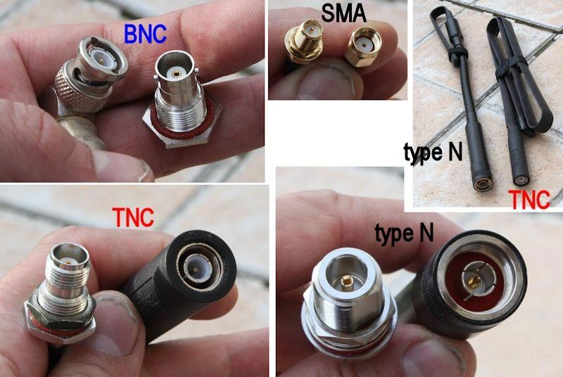
F, BNC, TNC, N, SMA, SMB, and U.FL Families
| Connector | Impedance | Coupling | Typical Uses | Advantages | Key Notes |
|---|---|---|---|---|---|
| F | 75Ω | Threaded | CATV, TV, cable broadband | Simple, low-cost, ideal for 75Ω systems | Not ideal for frequent mating or general RF testing |
| BNC | 50Ω / 75Ω | Bayonet | RF test, instruments, video, SDI | Fast connection, easy to use | Match the correct 50Ω or 75Ω version |
| TNC | 50Ω | Threaded | RF, antennas, industrial, vibration environments | Secure locking, better vibration resistance than BNC | Frequency performance depends on the exact model |
| N-Type | 50Ω | Threaded | Antennas, base stations, wireless, outdoor RF | Rugged and suitable for larger low-loss coax | Large and heavy for compact equipment |
| SMA | 50Ω | Threaded | High-frequency RF, microwave, test equipment, wireless modules | Compact, strong high-frequency performance | Distinguish SMA vs. RP-SMA and Plug vs. Jack |
| SMB | 50Ω / 75Ω | Snap-On | GPS, communication modules, internal RF links | Small and quick to connect | Less secure than threaded types in vibration |
| U.FL | 50Ω | Micro Snap-On | Wi-Fi, Bluetooth, GPS, cellular modules | Ultra-compact, ideal for PCB and micro-coax | Sensitive to repeated mating, pull force, and strain |
Match Connector Impedance, Frequency, Cable Size, and Environment
The selection of coaxial connectors directly determines the final performance of the entire transmission link and can be summarized in the following four points:
Impedance Matching: Mechanical Compatibility ≠ Electrical Compatibility
The first step in selection is to ensure that the connector’s impedance matches that of the entire link. Connectors must not be mixed; for example, while 50Ω and 75Ω BNC connectors look extremely similar and may be forced together mechanically, using them interchangeably will cause severe impedance discontinuity, leading to signal reflections, a surge in standing wave ratio (SWR), and compromised signal integrity.
Frequency Range: Must Cover the System’s Highest Frequency
Connectors have a defined upper frequency limit; when selecting a connector, the “connector’s rated frequency” must be greater than or equal to the “system’s highest operating frequency.” For example, standard BNC connectors are typically suitable only for frequencies below 4 GHz, while SMA connectors can reach up to 18 GHz. N-type, 3.5 mm, or 2.92 mm connectors, on the other hand, are suitable for even higher frequency bands.
Cable Dimensions: Must Precisely Match the Cable’s Physical Structure
This is the most commonly overlooked aspect in cable assembly design. Connectors within the same series have specific tail configurations for different cables and must precisely match the cable’s center conductor diameter, dielectric layer diameter, shielding layer dimensions, and outer diameter. Forcing a mismatched fit can result in poor contact at the center pin, insufficient shielding clamping, or failure of stress relief.
Tip:When procuring B2B, never simply specify “SMA connector”; the cable model must be clearly stated.
Operating Environment: Comprehensive Consideration of Sealing, Vibration Resistance, and Mating Frequency
Select the connector’s mechanical structure and protection rating based on actual operating conditions. Outdoor base stations or antenna feedlines are exposed to rain, salt fog, and temperature fluctuations, so threaded connectors with an IP protection rating or weather resistance should be used; for equipment with limited internal space and no severe vibration, push-in or miniature connectors may be selected.
How Do You Choose Coax for an Application?
When selecting coaxial cable, you don’t need to first consider the application and then verify the system impedance, operating frequency, transmission distance, allowable loss, power, installation environment, and connectors.
The real goal isn’t to find the “best” coaxial cable, but to find the one that has low enough loss for your system, fits the installation space, is compatible with the connectors, and is suitable for the environment.
CCTV, Broadband, Antenna, GPS, Cellular, Wi-Fi, and Instrumentation
| Application | Impedance | Key Factors | Selection Guide | Key Notes |
|---|---|---|---|---|
| CCTV | 75Ω | Distance, video bandwidth, shielding | RG59 for short runs; RG6 for lower loss over longer runs | IP cameras often use Ethernet rather than coax |
| Broadband / CATV | 75Ω | Bandwidth, loss, shielding, environment | RG6 for general use; RG11 for longer, lower-loss runs | Check jacket and installation rating for outdoor or in-building use |
| Antenna | 50Ω | Frequency, distance, feed-line loss, power | Use lower-loss coax as frequency or cable length increases | Feed-line loss can reduce overall antenna system performance |
| GPS | 50Ω | Loss, shielding, size, connector | Micro-coax for internal links; control total loss for longer feeds | Active GPS antennas may require DC bias through the coax |
| Cellular | 50Ω | Frequency band, loss, space, environment | Flexible micro-coax for short internal links; low-loss coax for longer feeds | Select by actual frequency band and cable length, not just “4G/5G” |
| Wi-Fi | 50Ω | GHz loss, length, space | Thin flexible coax for short runs; lower-loss cable for longer runs | Recalculate link loss before extending micro-coax |
| Instrumentation | 50Ω | VSWR, insertion loss, frequency range, stability | Choose low-loss, impedance-matched cables with stable repeatability | Continuity alone does not prove RF performance |
Calculate Total Channel Loss and Installation Margin
The calculation of total path loss for coaxial cables and the provision of installation allowance can be summarized in the following four points:
Total path loss = Cable loss + Connector/adapter loss + Loss from other passive components
Do not rely solely on the “dB/100m” value listed in the cable data sheet. An actual link includes passive components such as connectors, adapters, and even splitters, all of which introduce insertion loss. Losses in the cable itself must be calculated using the formula: loss per unit length at the target frequency × actual cable run length.
Installation allowance must be provided; a “theoretically just enough” approach is strictly prohibited.
After actual installation, link performance will be affected by factors such as connector termination errors, cable bending, temperature changes, and long-term aging. The engineering design must satisfy the following: calculated link loss + design allowance ≤ maximum allowable system loss. The size of the margin must be determined based on the specific link budget and system specifications.
Connector quality directly affects the final insertion loss.
Impedance discontinuities and termination quality in connectors can further increase return loss and insertion loss, with these effects being more pronounced at high frequencies. In high-demand RF cable harness projects, it is not sufficient to merely verify that the cable itself meets specifications; the correct approach is to require suppliers to provide insertion loss and VSWR test reports for the complete assembly within the target frequency range.
What Should B2B Buyers Include in a Coax Cable Specification?
When purchasing coaxial cables in a B2B context, the common issue isn’t “failing to specify requirements,” but rather that the specifications are incomplete. For example, if you only specify “RG58 cable, SMA connector, 1 m,” the supplier can certainly produce a cable, but you won’t know whether it meets your requirements for frequency, loss, environmental conditions, and consistency.
The correct approach is to define the coaxial cable assembly as a complete cable assembly.
A complete specification should cover, at a minimum, materials and mechanical structure, electrical performance and testing, environmental requirements, and traceability.
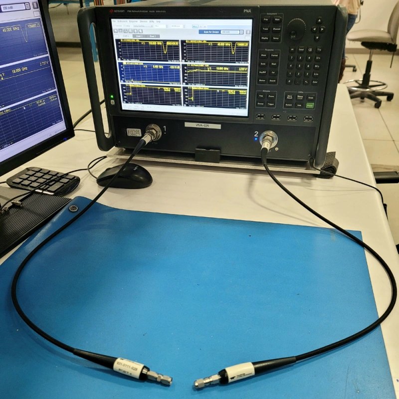
Cable Part Number, Connector, Length, VSWR, Insertion Loss, and Testing
| Specification | What to Define | Why It Matters | Common Mistake |
|---|---|---|---|
| Cable Part Number | Manufacturer, exact part number, or full performance requirements | Prevents uncontrolled cable substitution | Specifying only RG58 or RG6 |
| Connector | Series, plug/jack, straight/right-angle, impedance, part number | Affects impedance, frequency performance, and reliability | Writing only “SMA” or “BNC” |
| Length | Finished length, measurement reference, tolerance | Ensures consistent assembly dimensions | Specifying length without tolerance |
| VSWR | Maximum value and test frequency range | Verifies impedance matching and signal reflection | Writing only “Low VSWR” |
| Insertion Loss | Maximum loss at specified frequencies or bands | Shows actual loss of the complete cable assembly | Checking cable attenuation only |
| Testing | Continuity, Hi-Pot, VSWR, insertion loss, sweep test | Defines inspection and acceptance requirements | Setting performance limits without a test method |
Environmental, Compliance, Packaging, and Traceability Requirements
1. Environmental Requirements
Core Principle: Requirements must be defined based on real-world usage scenarios; unnecessary test items should not be added indiscriminately, as this will increase costs and extend lead times.
Application Differences: Standard indoor cabinets do not require salt spray or extreme vibration testing, whereas automotive, outdoor, or aerospace projects require strict environmental protection ratings.
2. Regulatory and Compliance Requirements
Differentiated Approach: RoHS/REACH, UL, and CE have distinct characteristics and should not be broadly lumped together as simply “compliant.”
Define as Needed: Certifications should be precisely specified based on the product’s target market, end devices, and actual customer requirements to avoid unnecessary accumulation.
3. Packaging Requirements
Protecting the Physical Structure: Packaging for high-performance RF cables must not only prevent impacts but also guard against excessive bending or deformation caused by external pressure. If a cable is compressed and deformed, its internal geometry will change, leading to impedance discontinuities and compromising VSWR and insertion loss performance.
Detailed Specifications: For mass-production projects, clearly define packaging formats, connector protective caps, anti-static requirements, label placement, and packing quantities.
4. Traceability Requirements
Classification by Risk Level:
- Consumer-grade/low-cost cables: Only part numbers and lot numbers are required.
- High-reliability/precision test cables: Serial numbers, production dates, raw material lot numbers, and individual VNA test reports for each cable must be provided.
Key Value: Ensures precise traceability in the event of quality issues and guarantees the repeatable performance of test devices.
Frequently Asked Questions About Coaxial Cable Types
Q1: Can 50-ohm and 75-ohm coaxial cables be connected?
They can be physically connected, but it is generally not recommended to mix them directly. Since 50Ω and 75Ω have different impedances, connecting them will create an impedance mismatch, which may increase signal reflection, VSWR, and loss. For high-frequency applications, long-distance transmission, or situations requiring high signal integrity, the impedance of the equipment, connectors, and cables should be matched.
Q2: Is RG6 better than RG59?
Not necessarily. RG6 is typically thicker than RG59 and, with similar construction, generally has lower loss per unit length, making it more suitable for longer distances; RG59 is thinner and more flexible, making it better suited for short distances and space-constrained environments. The choice should be based on frequency, length, and installation conditions, rather than simply determining which is “better.”
Q3: Does thicker coax always have lower signal loss?
Not necessarily, but with similar materials and construction, thicker coaxial cable generally has lower loss per unit length. However, loss is also influenced by frequency, conductor material, dielectric, and construction; therefore, you should ultimately compare the attenuation data of specific products at the target frequency.
Q4: What is the difference between coaxial cable and shielded wire?
Coaxial cable is a controlled-impedance transmission line in which the central conductor, dielectric, and outer conductor are designed in a coaxial configuration. It is primarily used for RF, video, and high-frequency signals. Standard shielded wire primarily uses a shield to reduce EMI interference and does not necessarily have a fixed characteristic impedance of 50Ω or 75Ω; therefore, it cannot simply be used as a substitute for coaxial cable.
Conclusion: Coaxial Cable Types: Impedance, Uses, and Selection
By now, you should have a clearer understanding of the structure, impedance, loss, connectors, and applications of different types of coaxial cables. Whether you’re selecting a replacement cable for a single device or making bulk purchases for a project, understanding the differences between 50Ω and 75Ω, the RG series, low-loss coaxial cables, and various connectors will help you make more reliable selection decisions.
As a professional cable and harness solutions supplier , Linkwings offers customized coaxial cable assemblies and technical support tailored to various RF, video, communications, and internal device connection needs. If you are looking for reliable coaxial cables or customized cable assembly solutions, please feel free to contact Linkwings—we can help you identify the most suitable solution.

Nicole
The founder of Linkwings Electronics.
10+ Years Experience | 1000+ Global Projects Completed
Specialized in:
- Custom Wire Harness Assembly
- Automotive & Industrial Cable Harness Manufacturing
- Precision Crimping & Terminal Processing
- OEM / ODM Wire Harness Solutions
Need help with your project?
Let Linkwingselec deliver your next wire harness solution.